Release pressure from both high and low side of compressor before installation or .

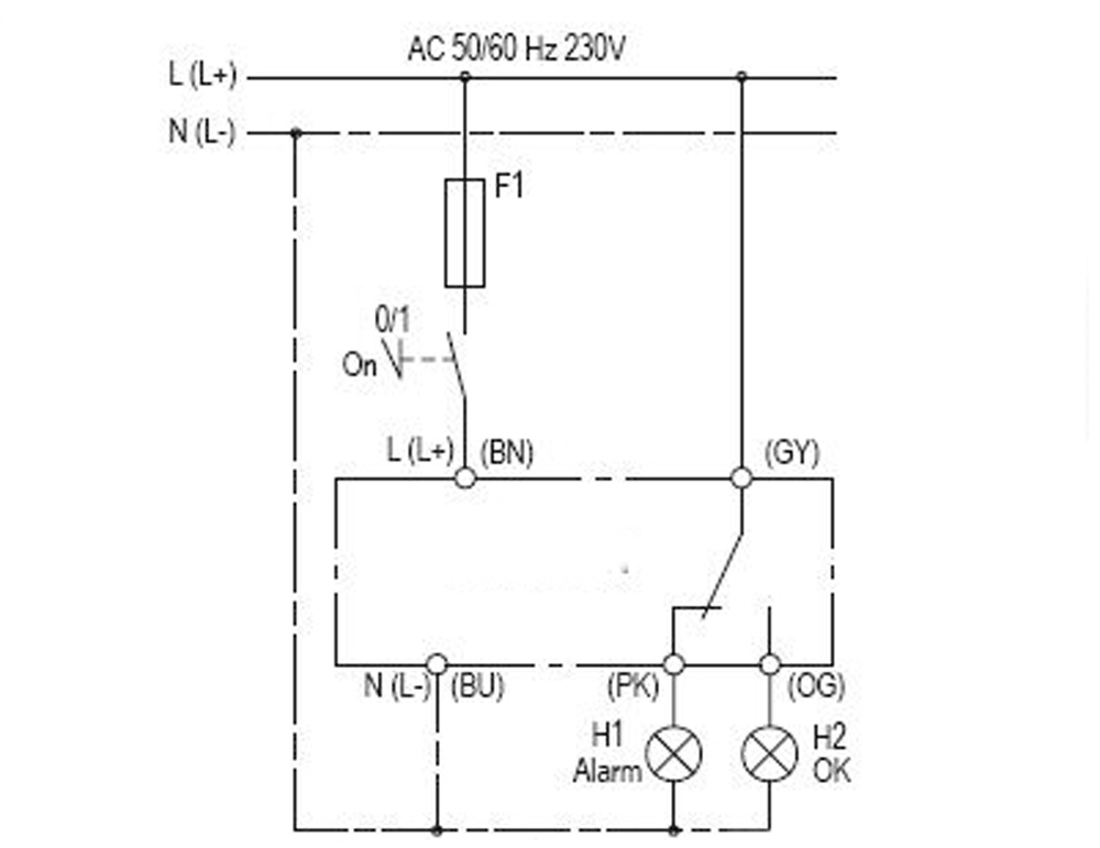
the compressor wiring diagram on the underside of the terminal box cover. ALL WORK ON COMPRESSOR AND REFRIGERATION SYSTEMS MUST BE CARRIED OUT BY BITZER TERMINAL BOX WIRING DIAGRAMS.
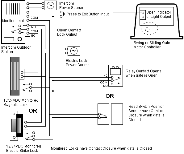
8. Electrical wiring / Equipment, and conform to current building codes. 7.
Clearances: A safe . Schematic depicting 3- Compressor DX CO2 Rack. •.
Schematic. WIRING DIAGRAM APPENDIX. TERMINAL BOX WIRING DIAGRAM.
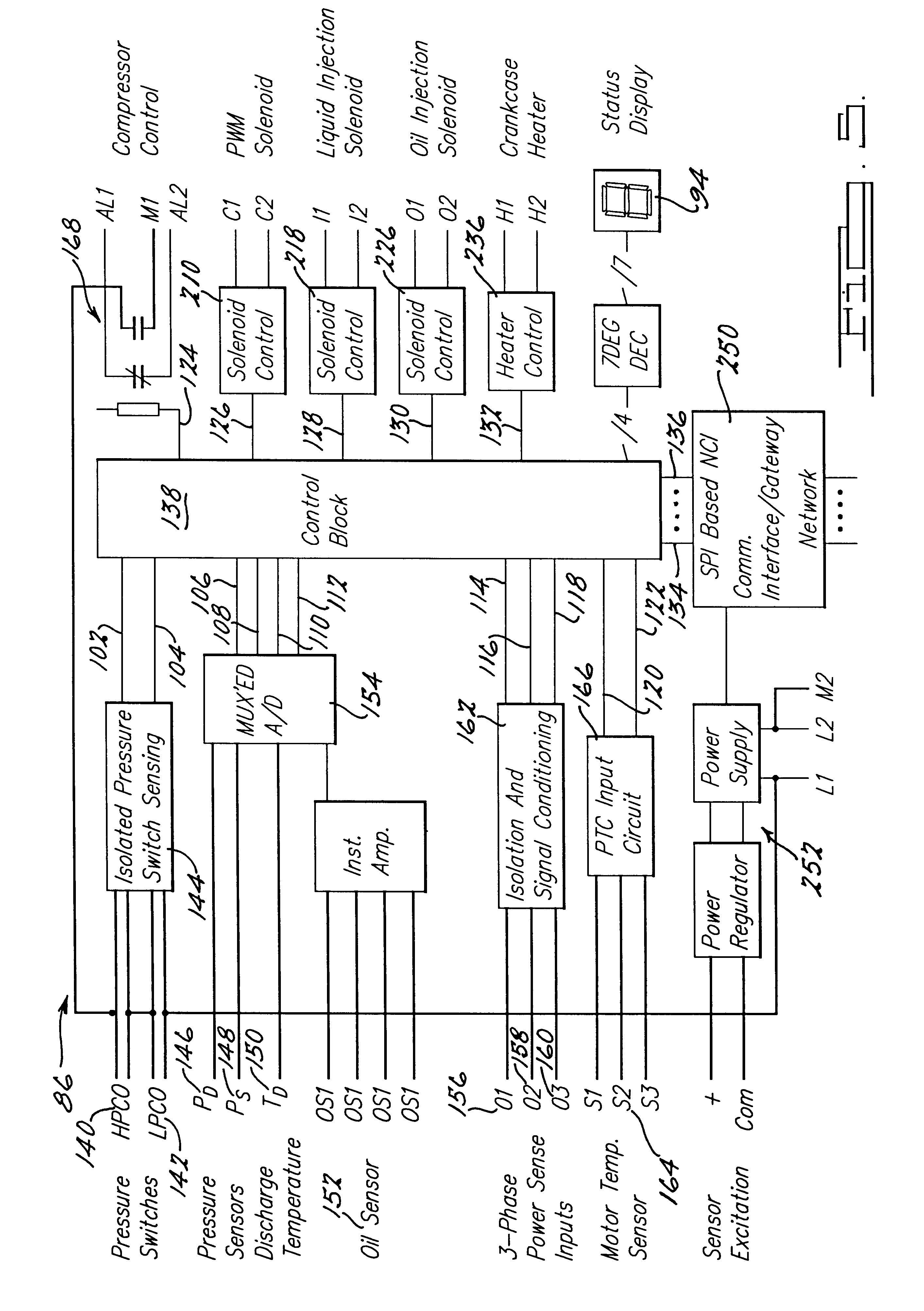
22 These guidelines are for retro-fitting scroll compressor racks with BITZER. Mounting Instructions & Diagrams. Electrical Connection & Wiring Diagrams .
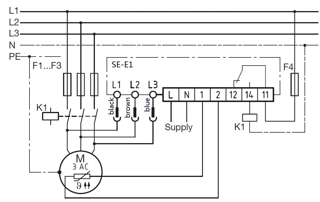
. Further compressor detail is available from the BITZER selection software.Jun 24, · An A-1 Compressor Technical Video for service technicians on “How To” wire a 9 lead v Copeland Compressor for Part Wind Start in the field. .
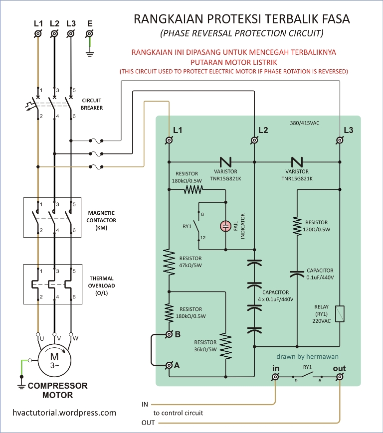
BITZER’s intention is that all electric work is performed by qualified and certified (where applicable) individuals and all standard electrical safety practices must be followed at all times. CS Screw Compressor Troubleshooting Guidelines 01 April Bitzer Compressor Wiring Diagram – Sometimes a photo can support engineers troubleshoot your design.
Especially if quality issues are suspected, such as soldering reliability, unsuitable connections, wrong polarities, and further problems which might be revealed in a photo. Search in BITZER catalogs and technical brochures on DirectIndustry and find the information you need in 1 click.
valve installed on the compressor body. The DTC valve liquid injection system is a low cost and reliable solution.
We hope you find an ideal compressor that fits your unique needs in this selection catalogue. Copeland Semi-Hermetic Compressor. hp S series.
6S 4S 3S 2S L series. 1.
General Information.Bitzer compressor protection module | SE-E1 Motor protector | Part-No_GOLDAIRAll BITZER catalogues and technical brochures – PDF Catalogue | Technical Documentation | Brochure