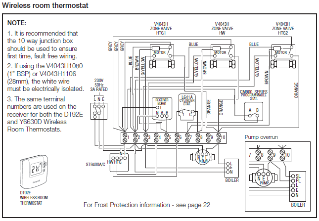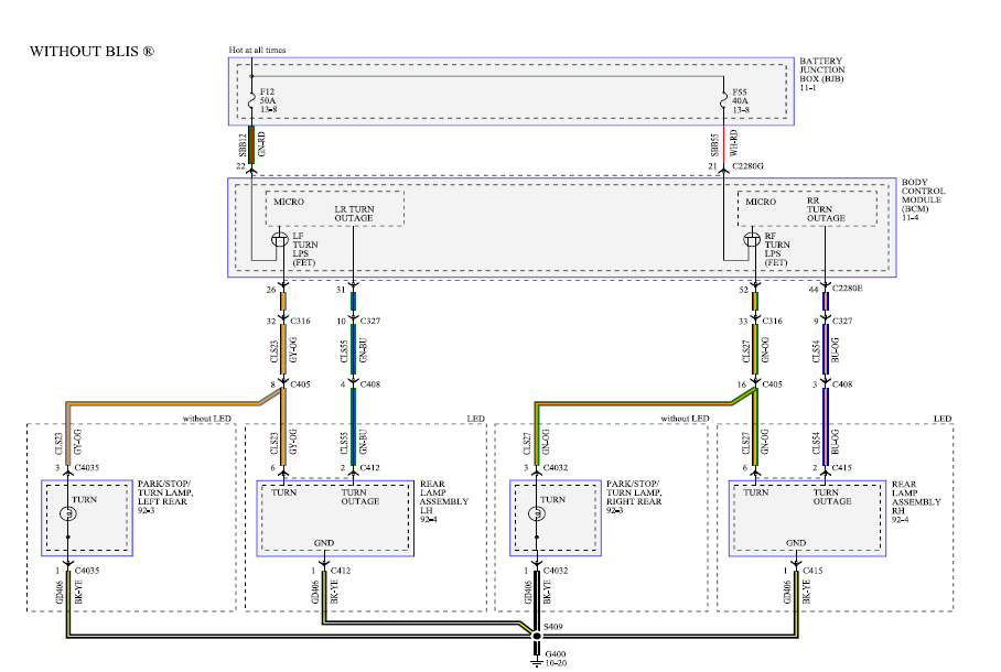
ISBN: Wiring diagrams provided herein are for information and reference only and . Firemen’s Telephone / Warden Station: SIGA-(M)CC1.
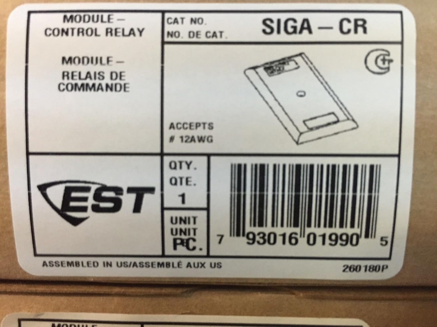
Click here to purchase the Edwards EST SIGA-CR Control Relay Module from Life Safety Consultants. We are the largest provider of fire alarm parts from top.
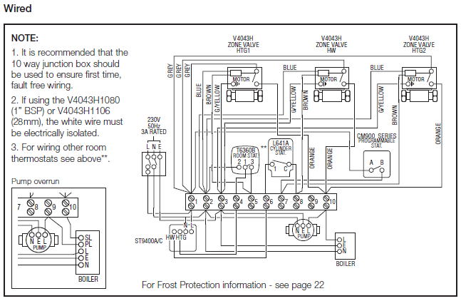
Signature – SIGA-CR Modules Connected to MR Series Multi Voltage onto an MR Figure 3: 24 VAC wiring diagram NC COM NO MR 0 24 . The SIGA-CR Control Relay Module is an addressable device that provides one Wire in accordance with “Wiring” on page 2.
3. Figure 2: Wiring diagram. 4) Make all wiring connections as shown in the wiring diagram.
5) Write the address . The Single Input Signal Module, Model SIGA-CC1, is a component of the.Note: The SIGA-CR is shipped from the factory as an assembled unit; it contains no user-serviceable parts and should not be disassembled.
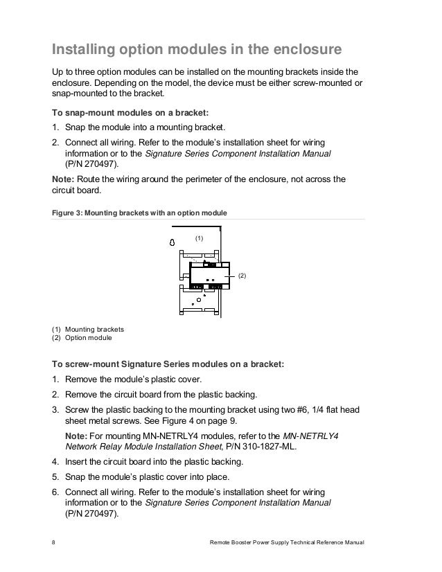
To install the module: 1. Verify that all field wiring is free of opens, shorts, and ground faults.
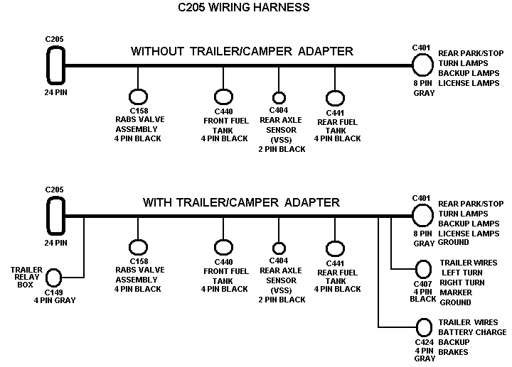
2. Make all wiring connections as shown in the wiring diagram. 3.
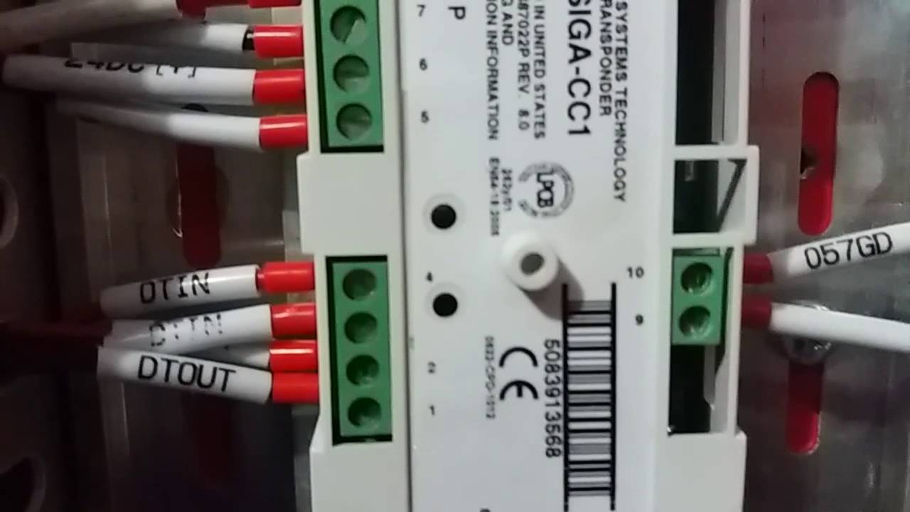
Write the address assigned to the module. (2) SIGA-CR module (3) Wall plate (4) # × 5/8 machine screw (2X) (5) #4 × 1/2 self-tapping screw Wiring Wire this device in accordance with applicable national and local codes, ordinances, and regulations.
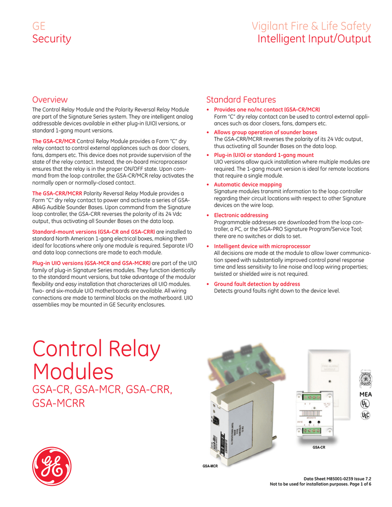
Notes limited source. • Refer to the Signature loop controller installation sheet for SLC wiring . The Control Relay Module and the Polarity Reversal Relay Module are part of the Signature Series system. They are intelligent analog addressable devices available in either plug-in (UIO) versions, or standard 1-gang mount versions.
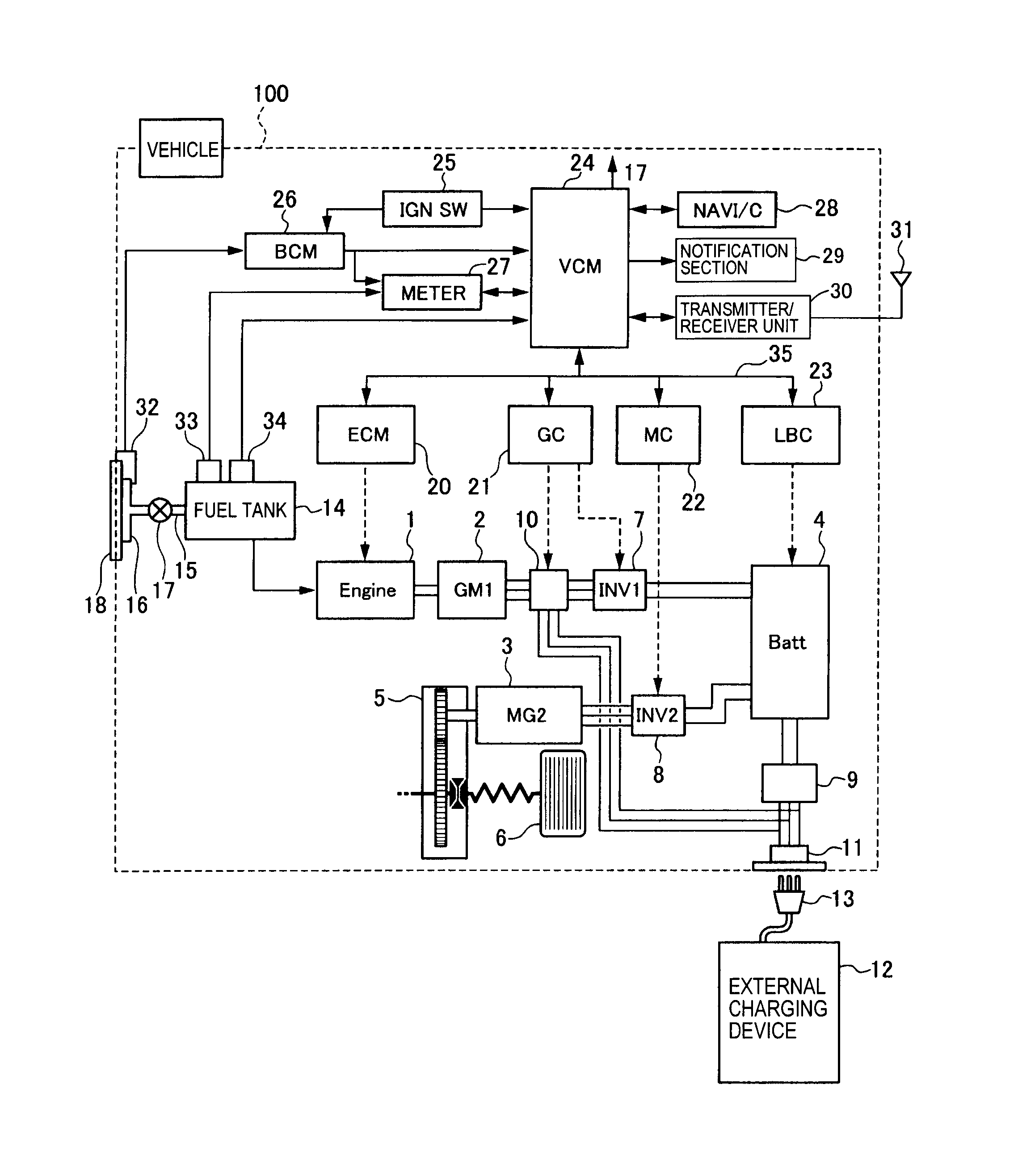
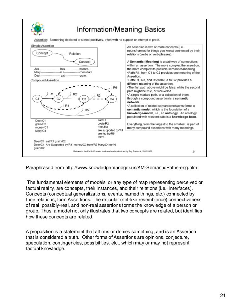
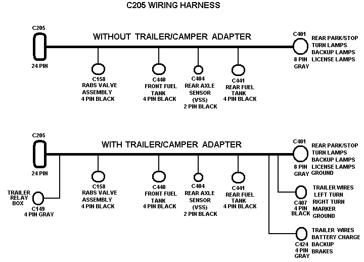
The SIGA-CR/MCR Control Relay Module provides a Form “C”. siga cr wiring diagram – A wiring diagram is a simplified traditional photographic representation of an electric circuit. It shows the elements of the circuit as simplified forms, and also the power and also signal links between the tools.
A wiring diagram usually provides information concerning the family member placement and also. All wiring connections are made to terminal blocks on the mother-board.
UIO assemblies may be mounted in GE Security enclosures. Control Relay Modules SIGA-CR, SIGA-MCR, SIGA-CRR, SIGA-MCRR Standard Features Provides one no/nc contact (SIGA-CR/MCR) Form “C” dry relay contact can be used to control external appli-.Cr Wiring Diagram – Detailed Wiring DiagramsMCQUAY 5ACV 30 CR INSTALLATION MANUAL Pdf Download.
