, and kVA for 11 kV distribution transformers and , , , shall be suitable for outdoor installation with three phase, 50 Hz, 11 kV or Current transformer connection box (Figure 1b) .. Terminate the cables in the correct terminal in accordance with the wiring diagram.
. Service Voltage 11kV.
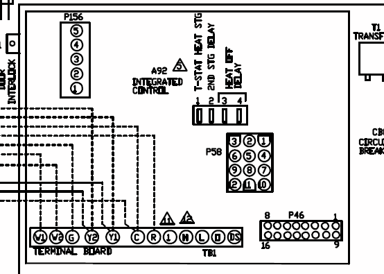
Current transformer connection box (Figure 1b) .. Terminate the cables in the correct terminal in accordance with the wiring diagram. .
Service Voltage 11kV. 6.
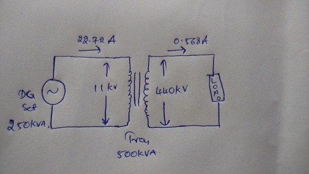
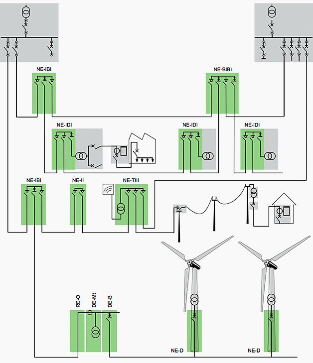
Diagram of user system for connection and. MV switchgear.
37 Diagram of the user installation. 40 MV switchgear solutions. 7.
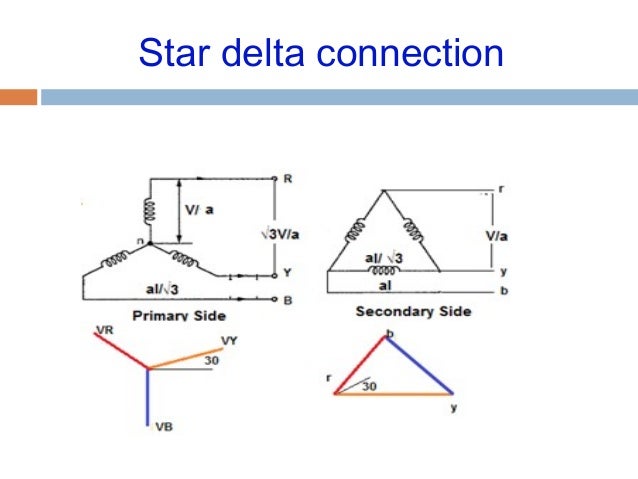
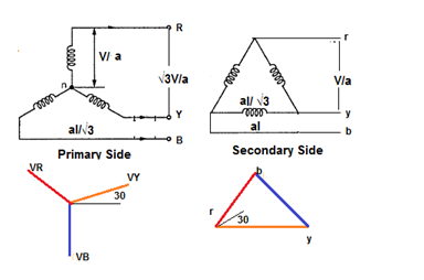
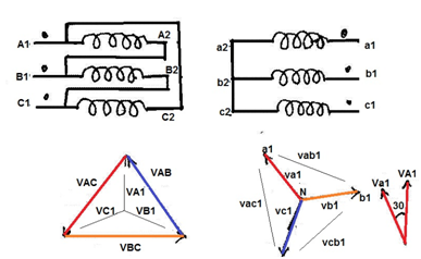
Power transformers. Meggering transformer wiring is emphasized because of the numerous of a transformer is relatively easy; the test connection diagram of.A three phase transformer or 3φ transformer can be constructed either by connecting together three single-phase transformers, thereby forming a so-called three phase transformer bank, or by using one pre-assembled and balanced three phase transformer which consists of three pairs of single phase windings mounted onto one single laminated core.
5. Distribution Transformer schematron.orgng 7.
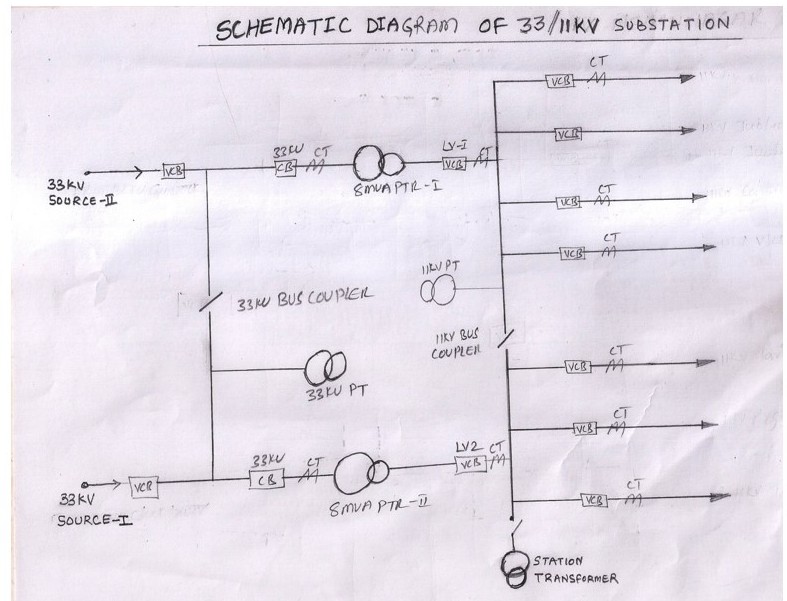
DO Fuse 8. Stay Wire 9. MV cable LV cable Fig shows the single line diagram of 11KV/V substation DP structure.

The single line diagram contains the Fig Layout and Single Line Diagram Of Pole Mounted Distribution Substation. Simple.
Its has three terminals for Voltages RYB and one for neutral. The all four terminals (incuding neutral) comes from secondary of PT (Potential Transformer), which step down the voltage i.e.
/ ratio PT will give output of Volt if the primary voltage is volt. 11kV/V Dry type Transformer and LT distribution Board etc. as detailed in the enclosed diagram with all protections like over current, earth fault and under voltage etc.
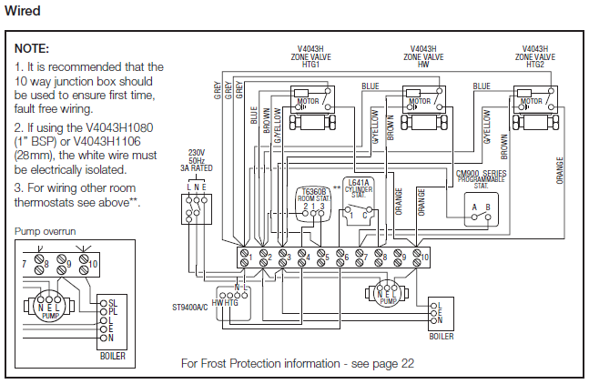
• The Substation should be suitable for outdoor application, compact and easily transportable and . The wiring shall be in accordance to the wiring diagram for proper functioning of the connected equipment.
Terminal blocks shall not be less than V grade and shall be piece-moulded type with insulation barriers. The terminal shall hold the wires in the .Part Transformers | ITACASingle-line diagram of AC transmission and distribution system
