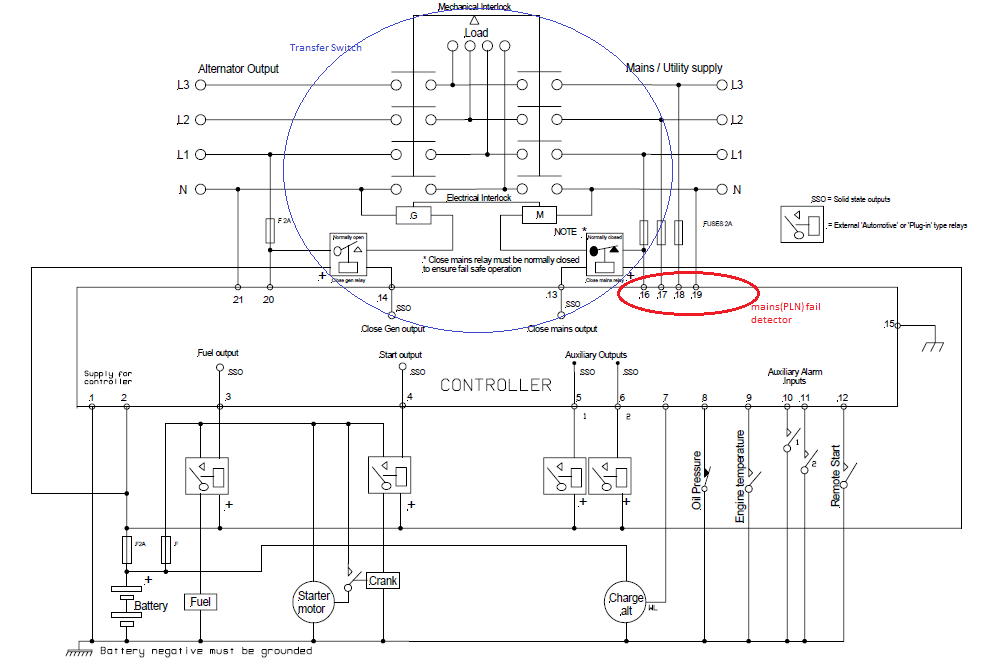
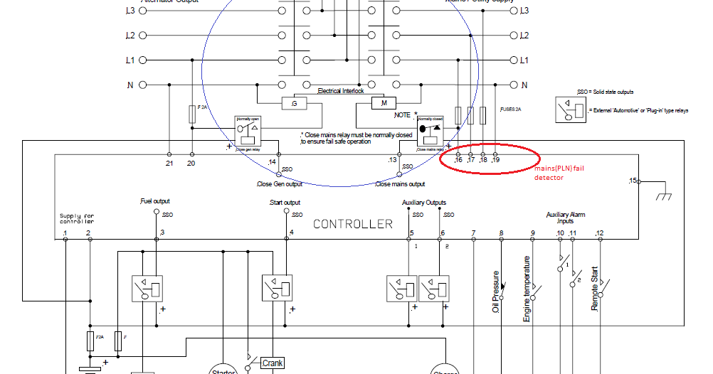
DSE Typical wiring diagram. ATS.
Load. From. Mains. Ct’s 5 amp secondary.
From. Generator.
51 52 53 Battery. Gen Volts. 43 44 45 41 39 The DSE & DSE have a number of different communication .
FIELD WIRING . DEEP SEA ELECTRONICS PLC maintains a policy of continuous.
DEEP SEA ELECTRONICS. INSTALLATION INSTRUCTIONS. ISSUE TYPICAL WIRING DIAGRAM.
ACCESSING THE FRONT PANEL. DSE MKII & DSE MKII Operator Manual must be addressed to Deep Sea Electronics Plc at the address above.
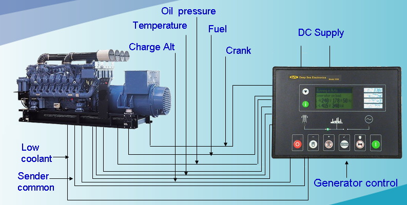
.. TYPICAL WIRING DIAGRAM.
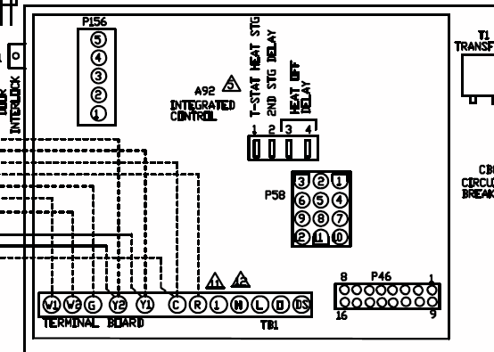
DSE Auto Mains (Utility) Failure Control Modules. View Product y Connection Diagram (PDF) · y Typical Wiring Diagram (CAD) (english) · y Typical .DEEP SEA ELECTRONICS INSTALLATION INSTRUCTIONS ISSUE 4 TYPICAL WIRING DIAGRAM ACCESSING THE FRONT PANEL CONFIGURATION EDITOR • Ensure the engine is at rest and the module is in STOP mode by pressing the Stop/Reset button.
• Press the Stop/Reset and Info buttons simultaneously.

DSE / Series Operators Manual 8 1 BIBLIOGRAPHY This document refers to and is referred to by the following DSE publications which can be obtained from the DSE. Cookies on the Deep Sea Electronics website We use cookies to ensure that we give you the best experience on our website.
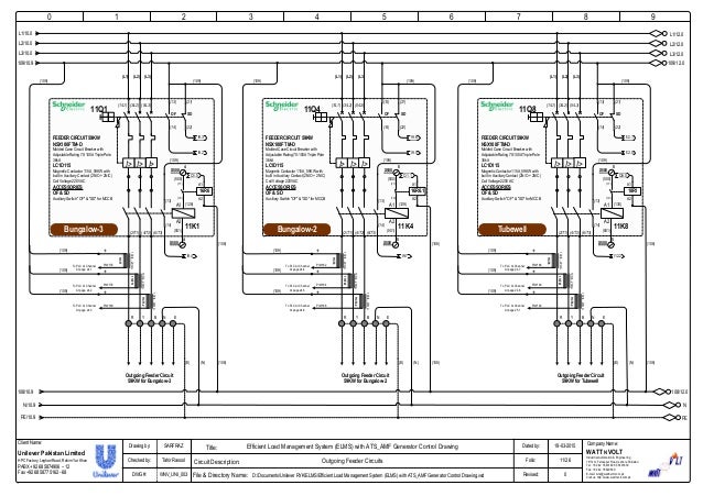
If you continue without changing your setting, we’ll assume that you have accepted the use of cookies on our website. DSE Typical wiring diagram ATS Load From Mains Ct’s 5 amp secondary From Generator 51 52 53 54 Battery Gen Volts 43 44 45 46 41 42 39 40 Generator Output D. DEEP SEA EL ECT RO NICS INSTALLATION INSTRUCTIONS ISSUE 11 TYPICAL WIRING DIAGRAM ACCESSING THE FRONT PANEL CONFIGURATION EDITOR • Ensure the engine is at rest and the module is in STOP mode by pressing the Stop/Reset button.
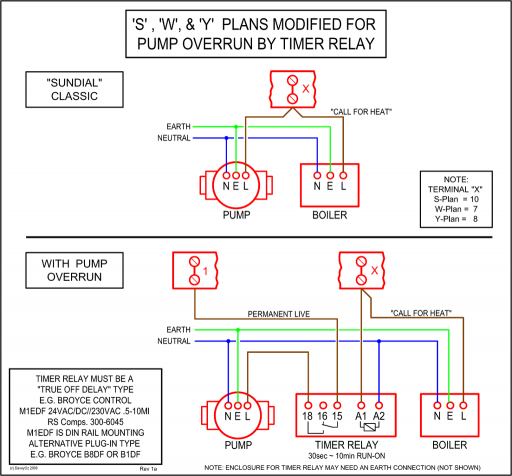
• Press the Stop/Reset and Info buttons simultaneously.DSE MKII | Auto Mains (Utility) Failure Control Modules | DSEGenset | Deep Sea ElectronicsDSE | Auto Mains (Utility) Failure Control Modules | DSEGenset | Deep Sea Electronics