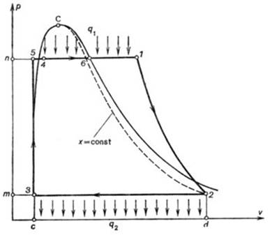
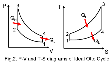
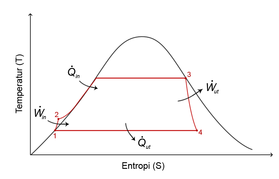
Rankine Cycle – pV, Ts diagram. The Rankine cycle is often plotted on a pressure volume diagram (pV diagram) and on a temperature-entropy diagram (Ts.
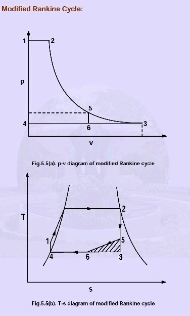
Figure Rankine power cycle with two-phase working fluid [Moran and Shapiro, Fundamentals of Engineering Figure Rankine cycle diagram. Download scientific diagram | P-V diagram of rankine cycle from publication: Thermal Analysis of Steam Turbine Power Plants | Steam are a major energy. The Rankine cycle is a model used to predict the performance of steam turbine systems.
It was also used to study the performance of reciprocating steam. Download scientific diagram | P-V diagram of rankine cycle from publication: Thermal Analysis of Steam Turbine Power Plants | Steam are a major energy.at state 1’ (refer T-s diagram) and deliver saturated liquid at state 2’.
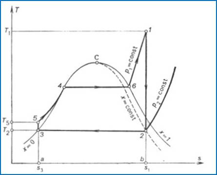
It is much easier to completely condense the vapor and handle only liquid in the pump. 2) In the rankine cycle, the vapor may be superheated at constant pressure from 3 to 3” without difficulty. In a .
The following ideal rankine cycle pv diagram pic have been authored. You can easily down load this amazing graphic for your portable, netbook or desktop pc. You also can easily bookmark this page to you favourite bookmarking sites.
at state 1’ (refer T-s diagram) and deliver saturated liquid at state 2’. It is much easier to completely condense the vapor and handle only liquid in the pump.
2) In the rankine cycle, the vapor may be superheated at constant pressure from 3 to 3” without difficulty. In a Carnot cycle .
In the Rankine cycle, the mean temperature at which heat is supplied is less than the maximum temperature,, so that the efficiency is less than that of a Carnot cycle working between the same maximum and minimum temperatures. The heat absorption takes place at constant pressure over, .
Rankine cycle – Ts diagram. The Rankine cycle is often plotted on a pressure volume diagram (pV diagram) and on a temperature-entropy diagram (Ts diagram)..
When plotted on a pressure volume diagram, the isobaric processes follow the isobaric lines for the gas (the horizontal lines), adiabatic processes move between these horizontal lines and the area bounded by the complete cycle path.Rankine Power CyclesIdeal Rankine Cycle Pv Diagram – schematron.org