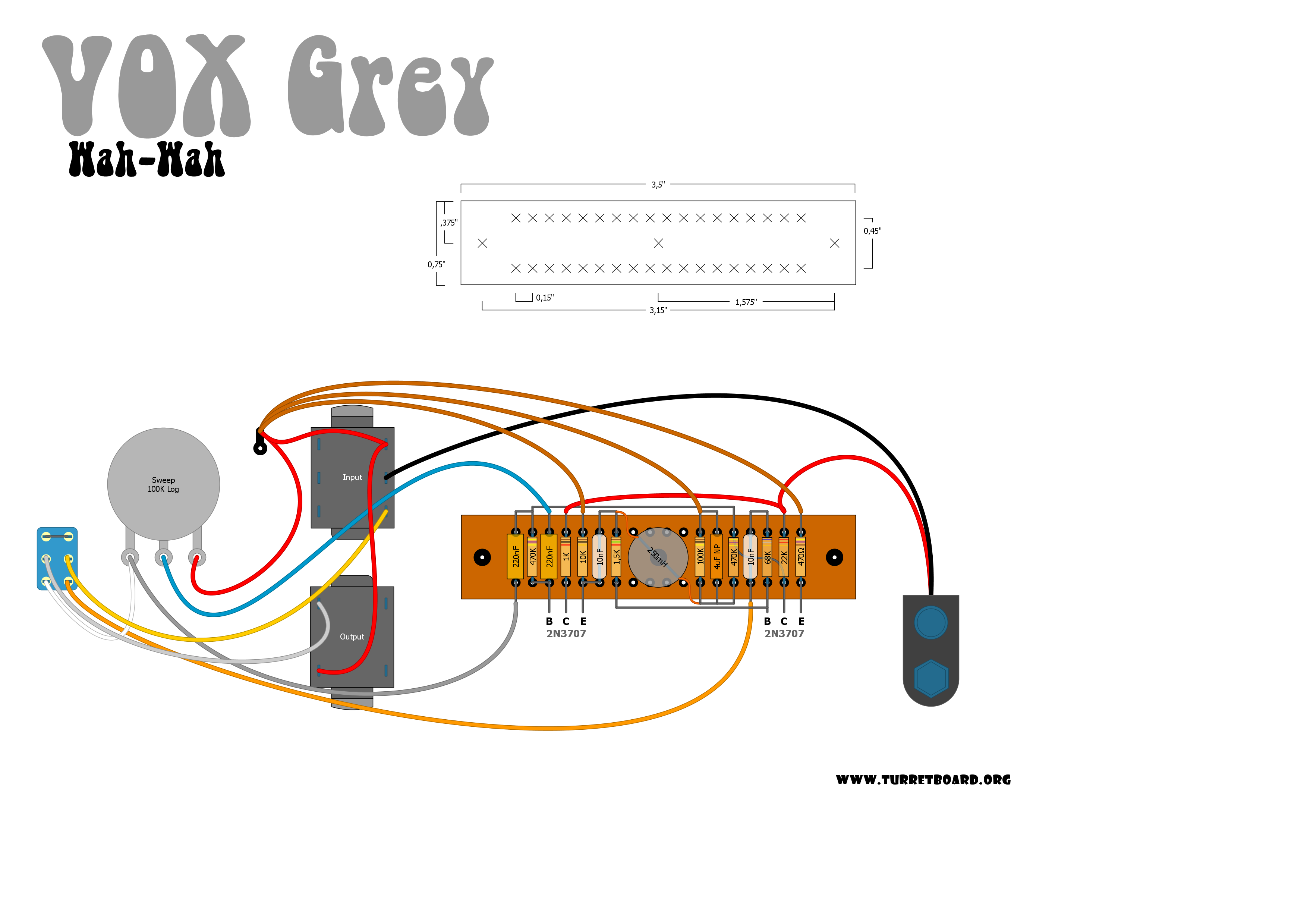
For this project you can replace the circuit board in your exsisting wah pedal with a Inductor Wah Wah wiring diagram with Range Switch and Toggle Switch.
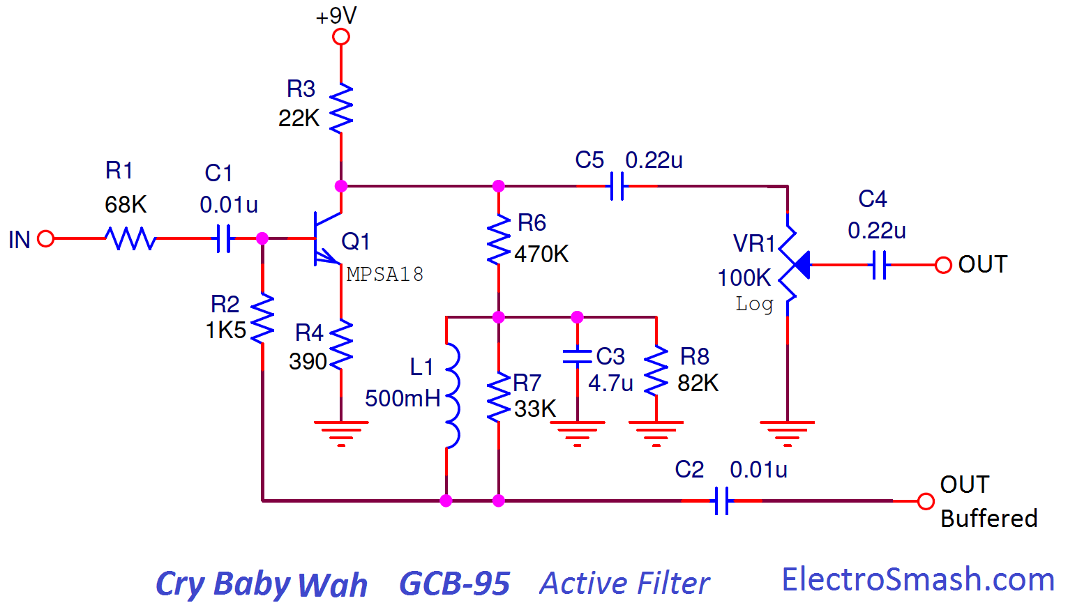
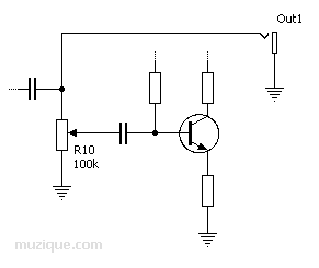
The stock “wah” pedal has been around since at least the early 60’s. The original was the Vox style inductor based wah circuit, followed by others, most notably .. Using the following schematic, we’ll look at what happens.
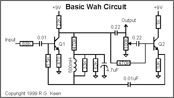
The Wah-Wah Effect, Vox V Circuit, Frequency Response, V Layout, Circuit The V is a Wah-Wah pedal designed by Lester Kushner and Brad The V simple schematic can be broken down into two blocks: Input Stage and . The stock “wah” pedal has been around since at least the early 60’s.
The original was the Vox style inductor based wah circuit, followed by others, most notably .. Using the following schematic, we’ll look at what happens. Details; Instructions; Schematic; Reviews.
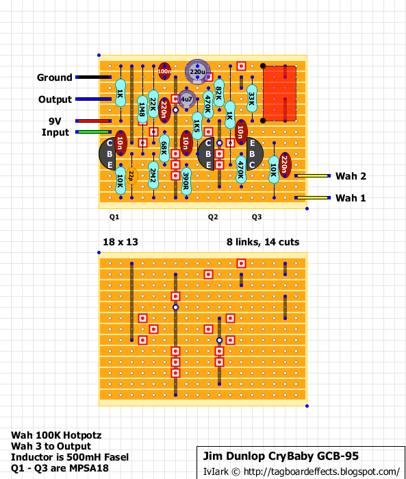
The BYOC wah kit gives you all the right parts for you need for the vintage wah that current mass produced models just.This wah has trim pots to tune in great sounds and also capacitor placements to vary the tone range of the wah. This will drop-in to any Dunlop or Vox wah pedal.
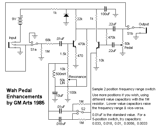
There are various wiring diagrams listed here to show a few ideas for switching the two inductors. Inductor Wah Wah wiring diagram with Range Switch and Toggle Switch Inductor Selector.
The Wah-Wah Effect, Vox V Circuit, Frequency Response, V Layout, Circuit Bias, Vox V Components Part List / Bill of Materials., Input Stage, Vox V Wah-Wah Analysis. The V is a Wah-Wah pedal designed by Lester Kushner and Brad Plunkett and released in by VOX.
Morley Diagrams, Schematics and Service Manuals – download for free! Including: morley ms schematic circuit electronic wiring diagram, morley abc box schematic diagram, morley aby switchbox selector schematic, morley attack control volume acv circuit diagram, morley auto wah pwa amp schematic diagram, morley bcv st chorus volume schematic.
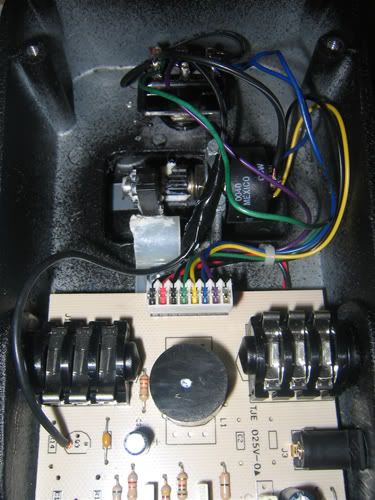
True bypass for s-’80s wah-wahs and other effects (diagram 1) 1) Unsolder the wires to the SPDT stock switch, remove it, and install the new 3PDT. 2) Find the input jack terminal “tip,” and unsolder and disconnect only the short wire that connects to the circuit input (marked #1 on the circuit board diagram).
UPDATE: The old wiring diagram contained errors (sorry, I wasn’t too familiar with electronics and wiring diagrams, this was one of my first projects and my first instructable). There were also questions about the blue wires going to the wah pot, I drew the wah pot to make things clear.Wah mod FAQ – schematron.orgSchematics | General Guitar Gadgets
