50 A (circuit.
Motor power kW. 15 kW at V AC 50/60 Hz AC kW at V AC 50/60 Hz AC LC1 D32 wiring datasheet, cross reference, circuit and application notes in pdf LC1 d32 contactor diagram LA7 D09 AM1-DP LC1 d wiring diagram. TeSys GV2-Circuit breaker-thermal-magnetic – 24 32 A – screw clamp terminals A at V for power circuit conforming to IEC A AC for. On LC1D09 – LC1D32, for spring terminals versions add ‘3’ to the catalog ..
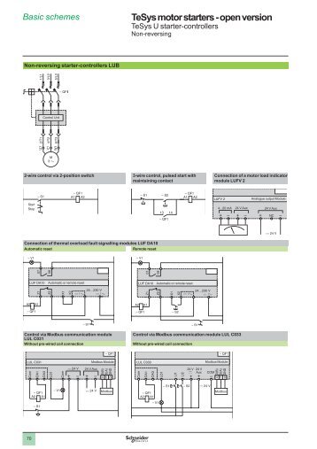
Installer to complete wiring for electronically interlocking contactor. Wiring Diagram for Telemecanique LC1 Contactor Replacements by US Breaker .
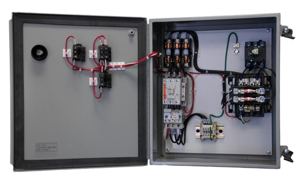
NC-F for cross references to the Telemanique LC1 D09 thru LC1 D32 or.The LC1D32 contactor is part of the largest selling line of contactors and starters in the world. The LC1D32 offers high reliability with long mechanical and electrical life and the most complete line of accessories in the industry. This book contains examples of control circuits, motor starting switches, and wiring diagrams for ac manual starters, drum switches, starters, contactors, relays, limit switches, and lighting contactors.
Each 3-pole device is pre-wired with line and load side power wiring for reversing applications. Each 4-pole device is pre-wired with load side power wiring a Use voltage codes from the “”Voltage Codes”” table below to complete the catalog number. Telemecanique LC1D32 Contactor with an AC coil voltage.
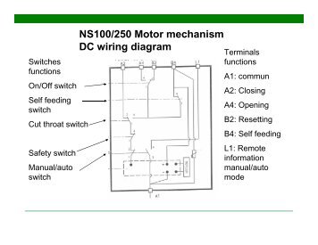
The LC1D32 is a 3 pole contactor with 1 NO and 1 NC base auxiliary contacts. – LC1 D32 wiring diagram. Abstract: LC1 contactor LA7 D09 54 overload schneider overload relay lrd 25 schneider thermal overload relay lrd 32 schneider electric LC1 D25 LC1 d32 contactor diagram LA7 D09 AM1-DP LC1 d wiring diagram.Wiring Diagram Book | Schneider ElectricHow to Wire a Contactor: 8 Steps (with Pictures) – wikiHow
