Typical Part Winding Start Wiring Diagram with an ICM and ICM NOTE: Use ICM for / VAC Control voltage only.
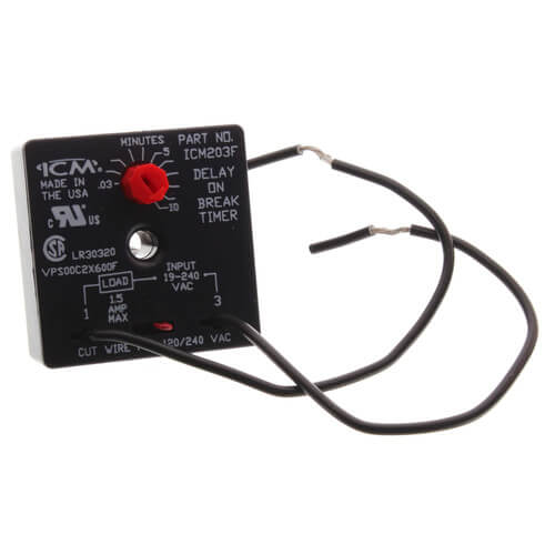
ICM ICM 6. 4.
3. 1.
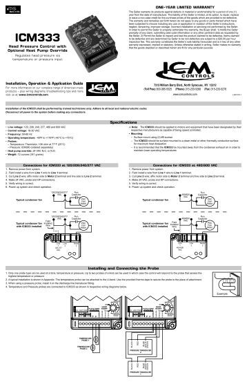
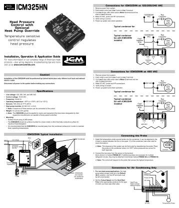
ICM Installation, Operation & Application Guide For more information on our wiring diagrams, troubleshooting tips and more, visit us at schematron.orgtrols. com Wire the contactor and optional control voltage monitoring as in Figures 2 .
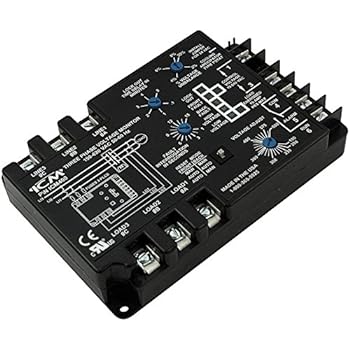
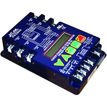
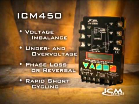
ICM Controls ICM 3-Phase Monitor, Fault Memory, LCD Setup and simple, 2-wire hookup adjustable timing universal voltage. made in United States . At power up, the ICM evaluates the incoming power for proper phase sequence, amplitude, and symmetry (voltage Simultaneous voltage display (an ICM exclusive).
– View all Control voltage LED • Fault LED Wiring diagram on unit. ICMPIN ICM SUSI. 50 AMPS Control Voltage.
– ICM Typical Part Winding Start Wiring Diagram with an ICM and ICM Control .ICM 3-Phase Voltage Monitor-Programmable ICM Stop Motor Burnouts! 3-Phase line voltage monitor with fault memory, high temperature LCD display, easy setup & clear diagnostic display of system faults, VAC operation.
Control Mode With control mode set to OFF, the load will energize if no 3- phase fault conditions exist; with control mode ON, the load will energize if no fault conditions exist and control voltage is present at terminals 1 and 3 of the ICM ON or OFF ON Based on wiring * Non-critical faults are faults such as High/Low Voltage and Phase Unbalance. View and Download ICM Controls SCL installation, operation & application manual online. Electronic.
labeled wires in matching wire terminals. See “Wiring Diagrams” section of this. manual (Pages ).
CAUTION!: Be sure exposed portion of wires does not touch other wires. Summary of Contents for ICM Controls SCL.
3. Wire the contactor and optional control voltage monitoring as in Figures 2 and 3 (below). • Use of terminals 1 and 3 is optional.
Connect voltage as shown in Figure 1 (below). mount the ICM in a cool. Using (2) #8 screws.
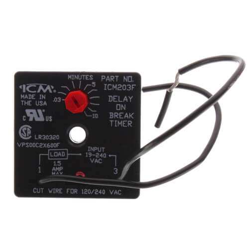
easily accessible location in the control panel. the ICM will be on line and will begin to monitor the system.
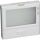
2. View and Download ICM Controls SC operating instructions online. non-programmable. SC Thermostat pdf manual download.
products – plus wiring diagrams, troubleshooting tips and more, visit us at schematron.org Parts Diagram. Up button. Summary of Contents for ICM Controls .ICM Controls 3 Phase Line Coltage Monitor ICM | eBayPART #: ICM – CONTROL MONITOR VOLTAGE V/3PH
