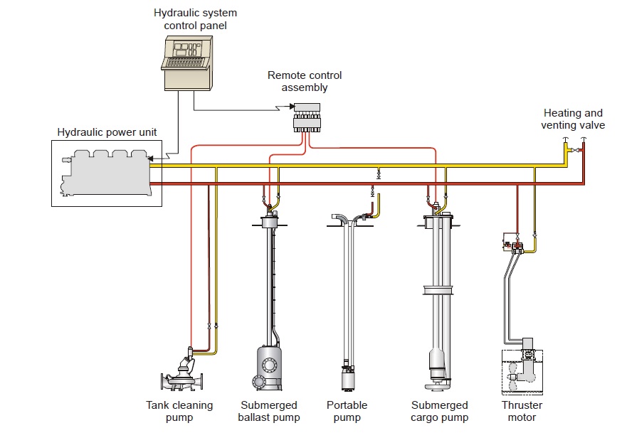
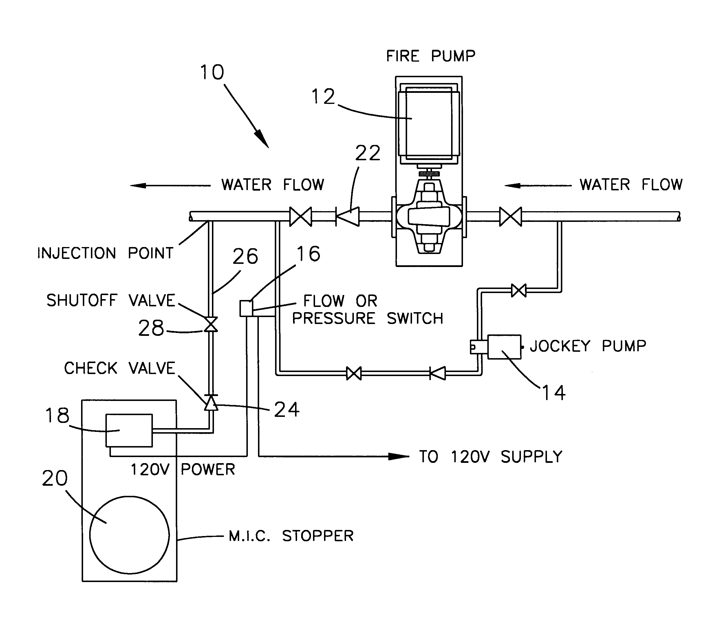
JOCKEY PUMP DRAINS AND VENTS TO DRW.
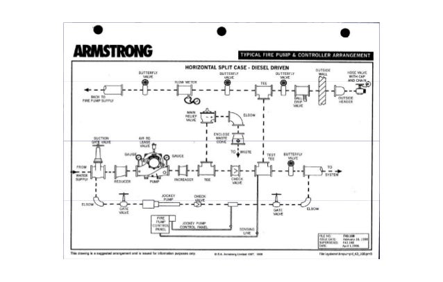
PIPING HIGH POINT VENTS AND LOW POINT .. PROCESS FLOW DIAGRAM FOR THE. B = Jockey Pump Sensing Line D = Jockey Pump Controller.
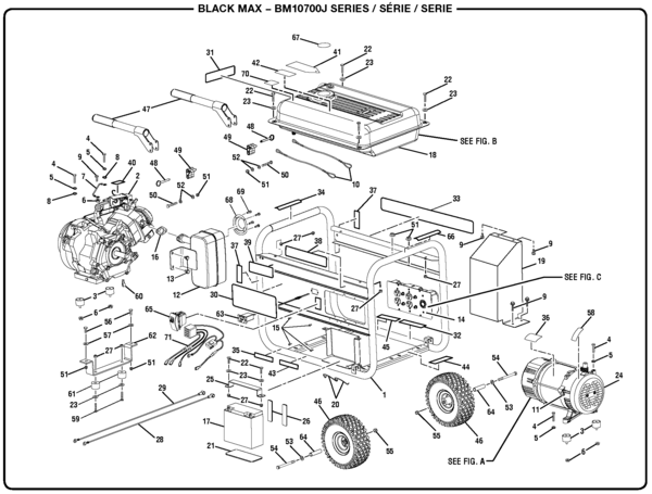
C commonly the pump controller is connected to the fire protection system by means of piping. Wiring / Main Electrical Service. • Fuel Tanks (Diesel).
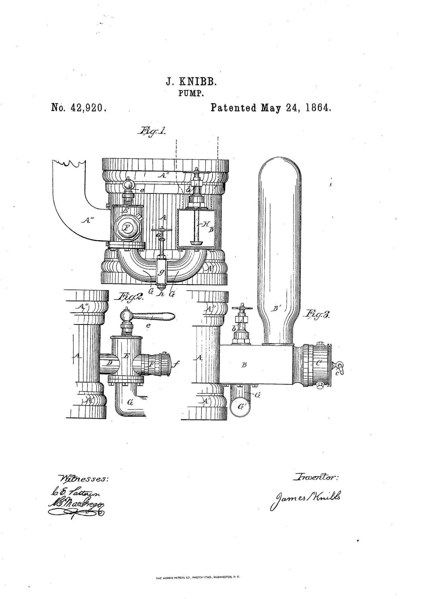
• Jockey Pump. • Relief Devices / Drains.
• Heaters or Ventilation. • Test Header Piping.
• Closed Loop. PIPING ENTRANCE.
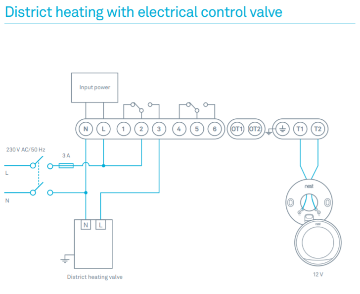
1/4″ NPT – Electrical Wiring Schematic. Jockey Pump The Jockey Pump Controller shall meet the requirements of the latest edition of.
and discharge permits easy-piping layout and pump installation. .
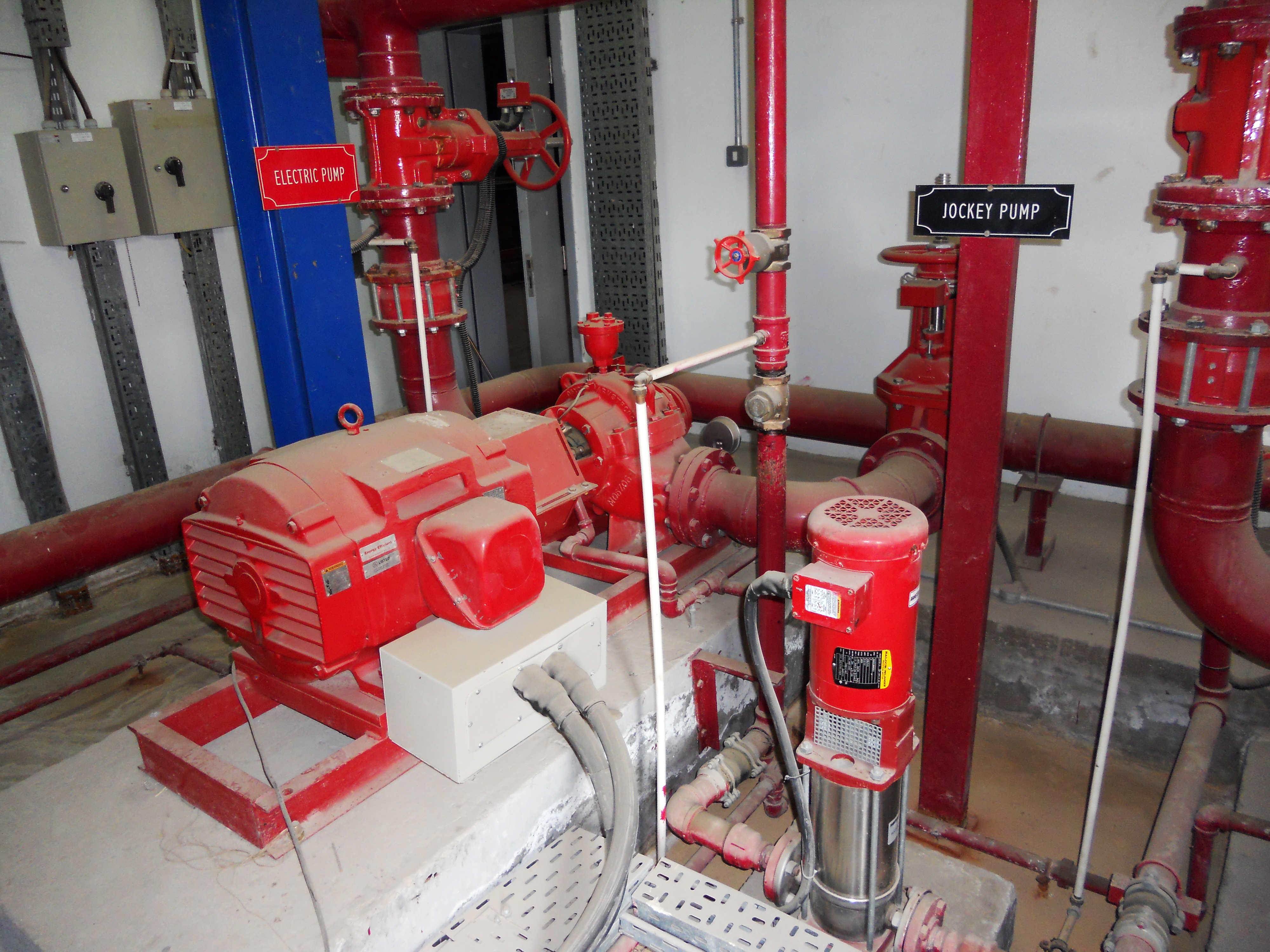
the pressure switch to start the Jockey pump is located in the. Jockey pump.PUMP MOTOR CONTROLLER General: The Model PMC is a fusible combination motor starter with a built in pressure switch for use with pump motors such as make-up pumps, booster pump, or `jockey’ pumps which are used with automatic sprinkler systems.
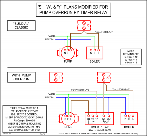
Some units are supplied with a circuit breaker in lieu of the fusible disconnect (switch and fuse block). The pressure sensing line connection for each pump, including jockey pumps, shall be made between that pump s discharge check valve and discharge control valve. This line shall be brass, copper, or series stainless steel pipe5/5(1).
Jockey pumps or sprinkler system pressure maintenance pumps are a low cost yet essential component of a fire pump sprinkler system. Typically the jockey pump is sized to 1% of the fire pumps rated flow.
There are several types of jockey pumps each having their advantages to a given application. The information provided here is for educational purposes only. Technically qualified personnel should install pumps and motors.
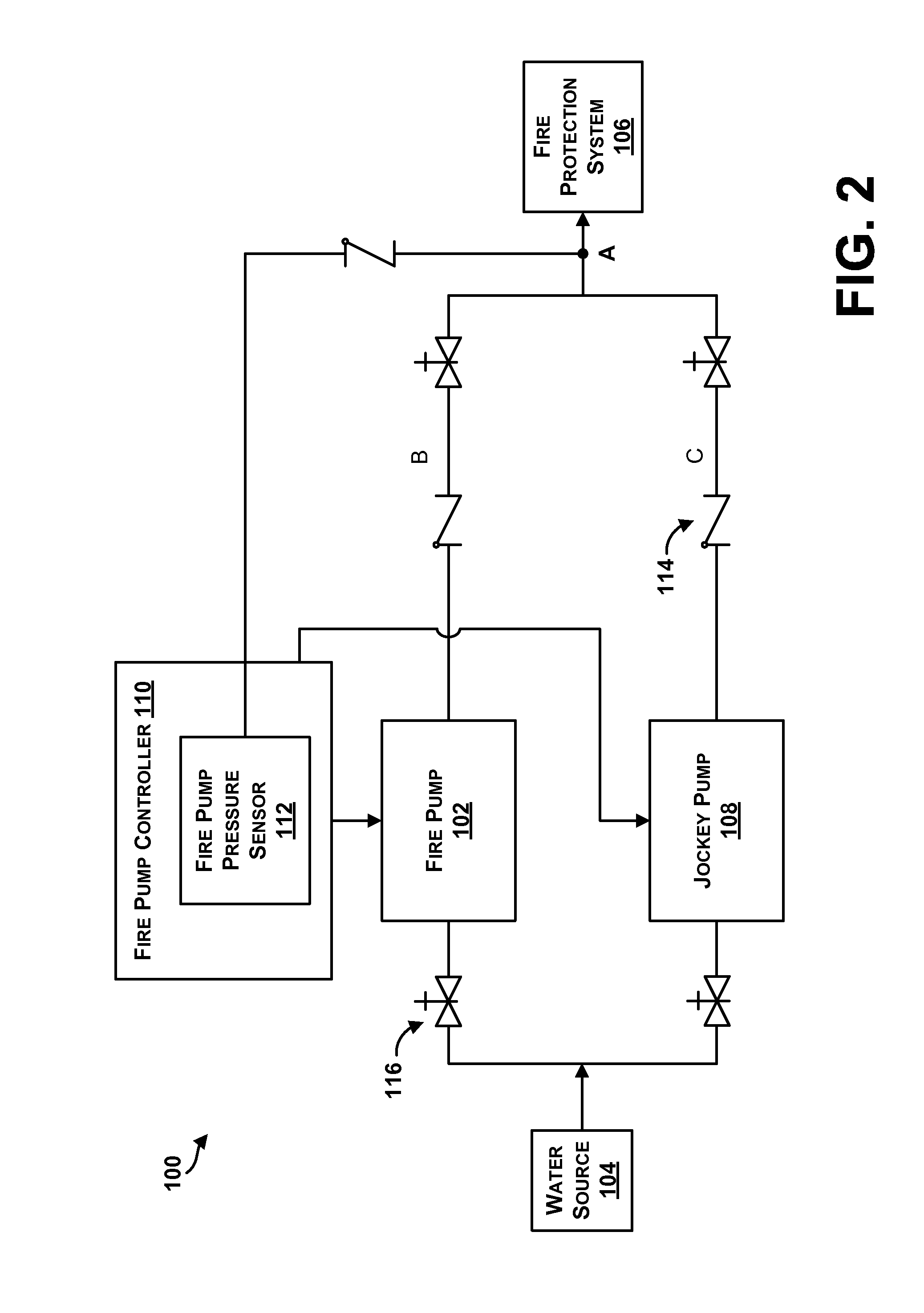
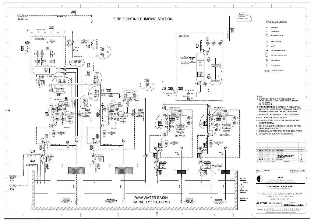
We recommend that a licensed contractor install all new systems and replace existing pumps and motors. Figure above reprsents typical piping and instrumentation diagram of pump.
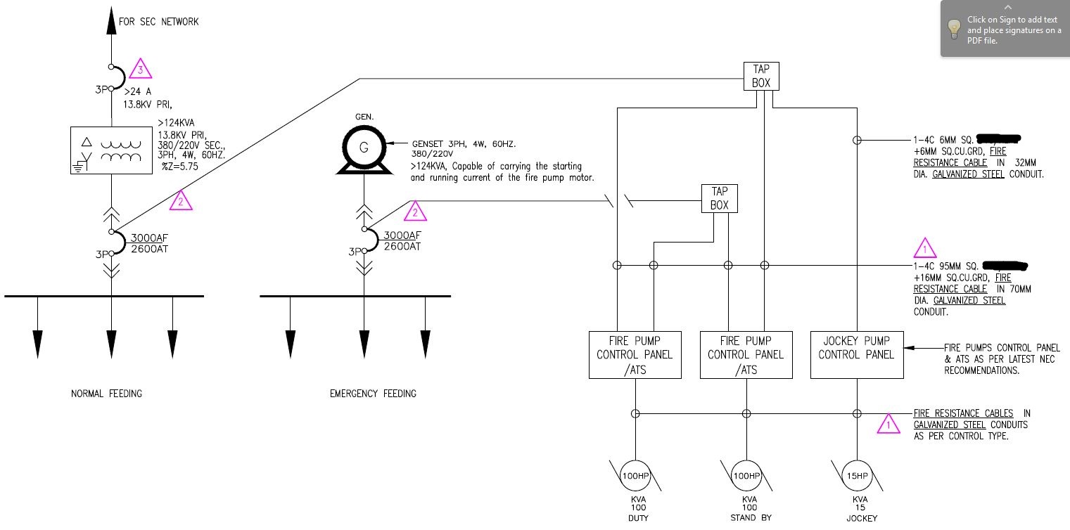
Pump should have: In our design basis, we stated that the capacity of jockey pump is 50 gpm (the capacity of main fire pump is gpm for electric motor fire fighting and diesel engine fire fighting, respectively).Flint and Walling Typical Piping DiagramsDiagrams –Typical Pump Installations