If any pieces are missing, contact your Garmin® dealer immediately.

. The following diagram illustrates the NMEA wiring used to connect your VHF.
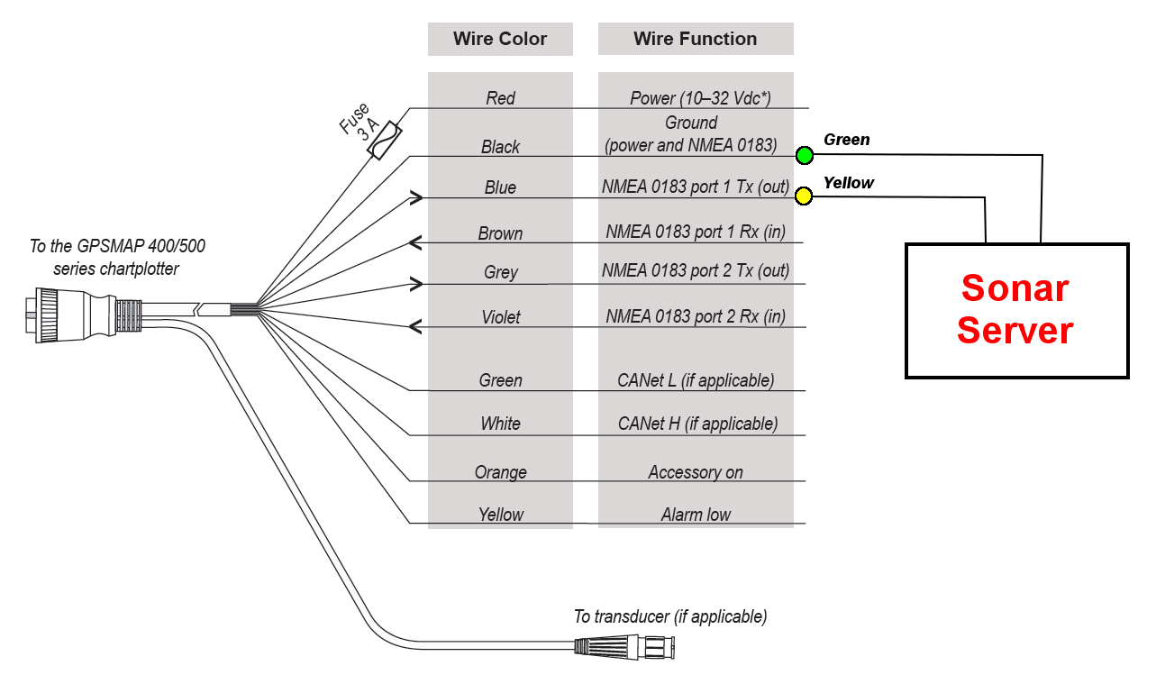
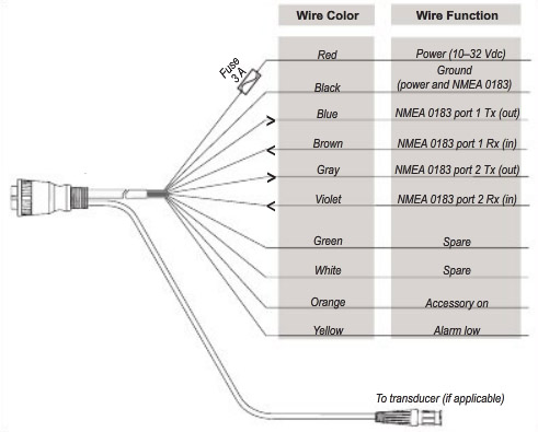
See the installation instructions for the NMEA device to identify the transmit See the table and wiring diagrams when connecting the data cable to NMEA. professional installer, or contact Garmin Product Support.
.. Refer to the wiring diagram of your NMEA device for wire identification. 2.
Connect the blue. Item.
Description. glyph icon. 12 Vdc power source.
glyph icon. Wiring harness. glyph icon.
NMEA compliant device. Item. Garmin Wire Function.
Garmin. Consult the installation instructions for your NMEA compliant device to identify NOTE: This diagram illustrates both sending and receiving connections .Technical Reference for Garmin NMEA Products 3 NMEA Fundamentals Building a NMEA Network The main communication channel of a NMEA network is a backbone to which your NMEA devices connect.
Use this NMEA cable for when you need to share numeric data on your boat. Wiring harness NMEA compliant device Item Garmin Wire Function Garmin Wire Color NMEA Device Wire Function Power Red Power Ground Black Data ground Tx/Rx Tx/Rx/B (-) Tx Blue Rx/A (+) Rx NMEA Connection Diagram.
The AIS wiring layout diagram on page 2 contains an example of the AIS connected to a Garmin chartplotter through a NMEA network.. garmin nmea wiring diagram,lowrance nmea wiring diagram,nmea connection diagram,nmea wiring diagram, Thanks for visiting our site, articleabove Nmea Wiring Diagram published by. 2 GPSMAP / Series Installation Instructions Mounting the GPSMAP / Series Chartplotter You can mount the GPSMAP / series chartplotters using one of two methods.
You can use the included bracket to bail mount the chartplotter, or you can use the included template and hardware to flush mount the chartplotter.GPSMAP and Series Installation Instructions – NMEA Connection DiagramIndex of /schematron.org