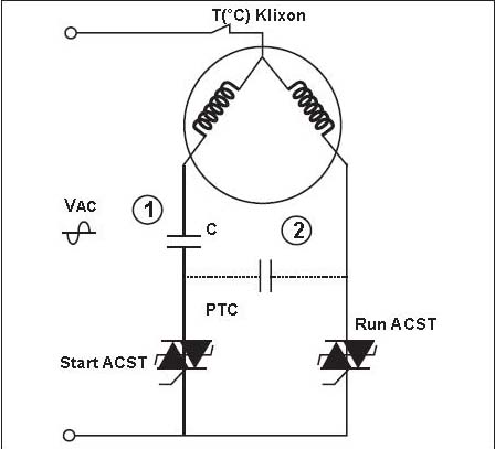
Air.
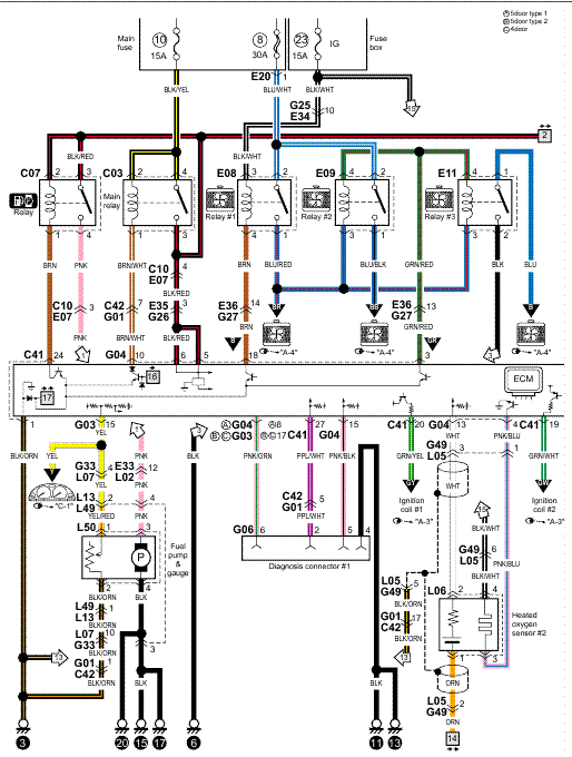
Conditioner. Schematic.
Diagram and. Electric.
Heater. Wiring.
Options. v, .
1. Phase, SCROLL COMPRESSOR.
ONLY). 1 .
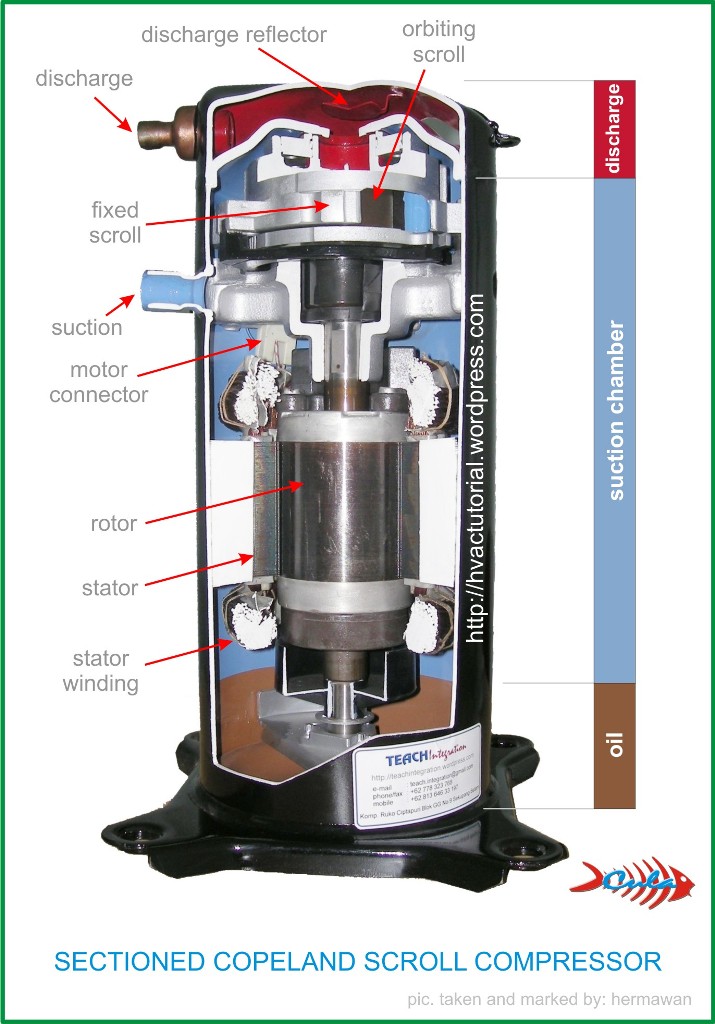
(COPELAND K1 SCROLL. Copeland Scroll compressors have a voltage tolerance of + 10%. Example: .
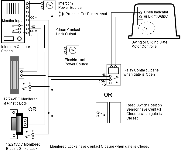
9 Air Conditioning Scroll Compressor Wiring Diagrams. – 15 HP.
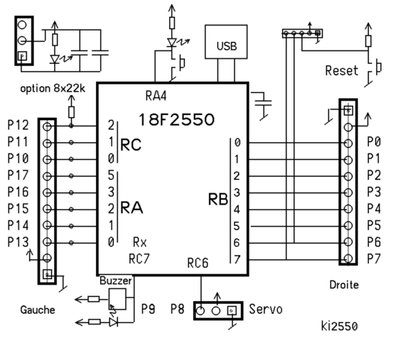
Hi there, Save hours of searching online or wasting money on unnecessary repairs by talking to a 6YA Expert who can help you resolve this. Assembly Instructions for Copeland Scroll™ compressors .
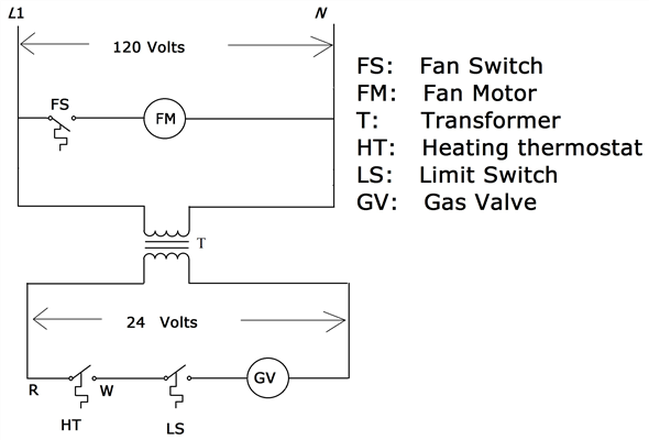
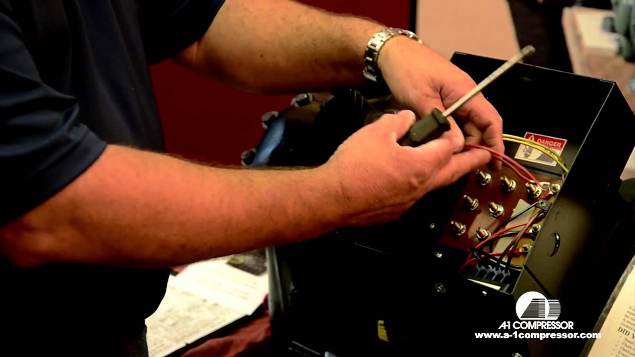
The compressor terminal box has a wiring diagram on the inside of its cover. Before connecting the.
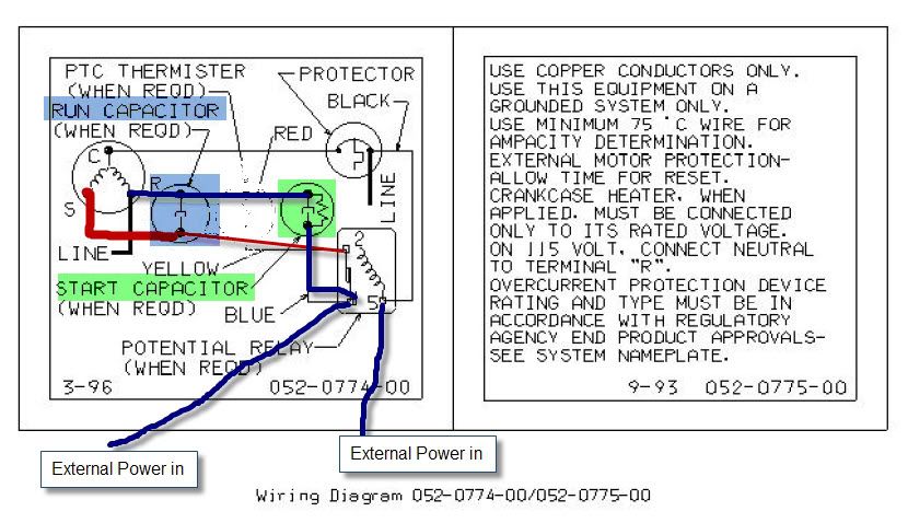
Refer to original equipment wiring diagrams. Care must be taken to ensure that wiring or .
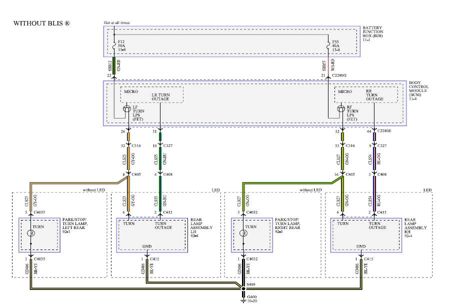
The Copeland Scroll compressor’s inherent.Find best value and selection for your Copeland SCROLL Compressor Wire Harness Connector search on eBay. World’s leading marketplace.
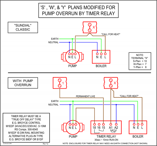
Copeland Scroll™ Wholesaler Product Guide Also Includes Replacement for Tecumseh and Bristol Compressors. Compressor Data Notes, Rating Points 14 ZB, ZF, and ZS Models 15 ZR Models 27 ZFH Models 59 Copeland® Brand to Copeland® Brand Quick Reference.
Compressor Controller inside the electrical enclosure near the compressor contactor (wire routing for compressor power wiring will be easier in this position). The maximum wire terminal screw torque is 7 in.
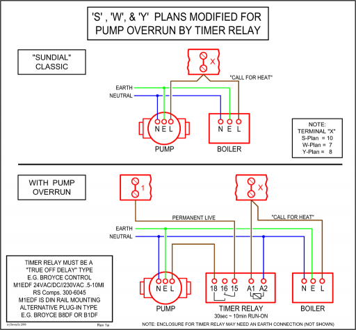
lbs. The Digital Compressor Controller will operate in any mounting orientation where the green POWER LED is at the top.
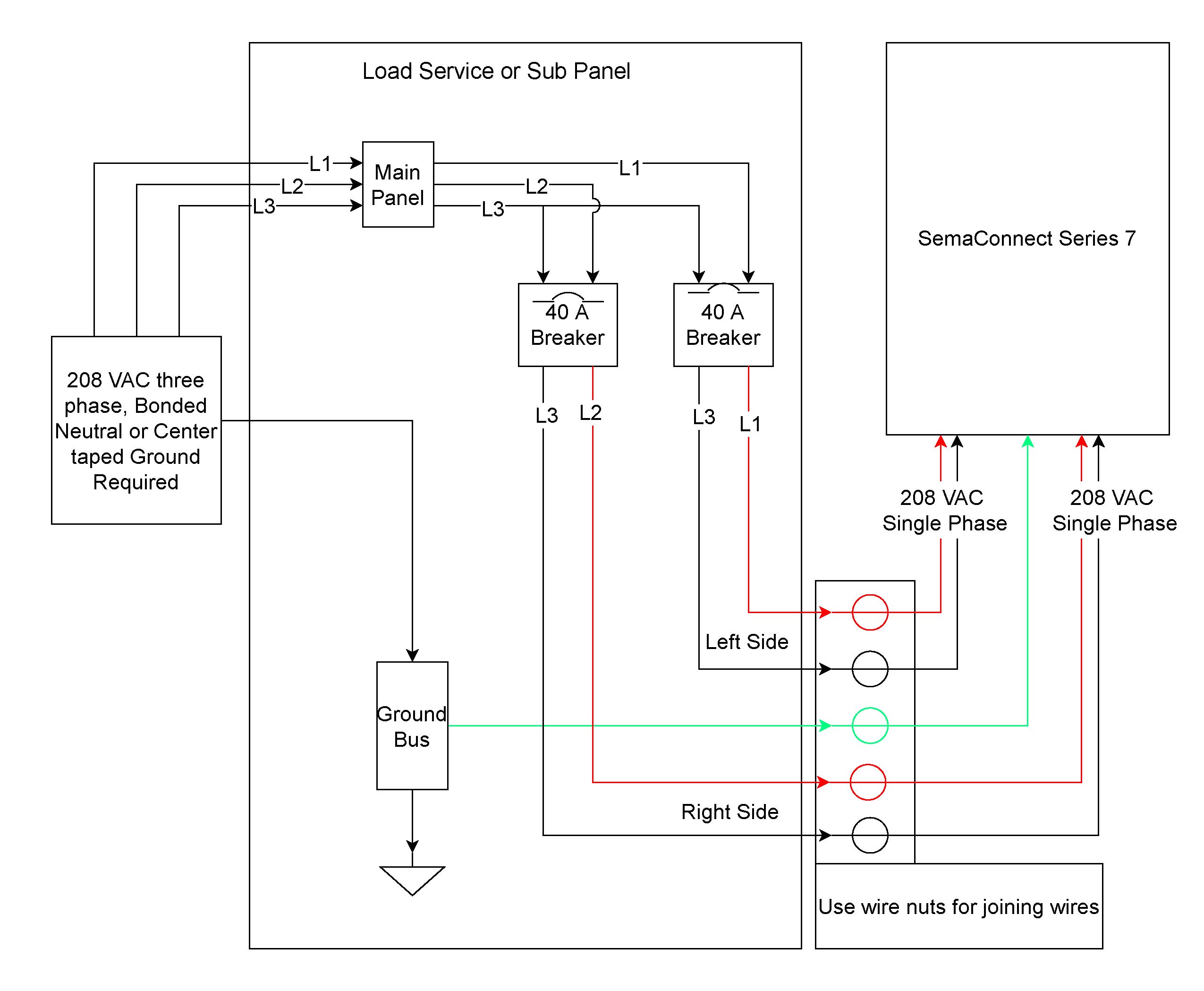
Jan 25, · 24vlts AC out of the board and through the wiring harness. In the rubber plug that plugs into the compressor, there is a rectifier that changes the voltage DC.
Do NOT put 24vlts AC to the solenoid. This will burn up the coil.
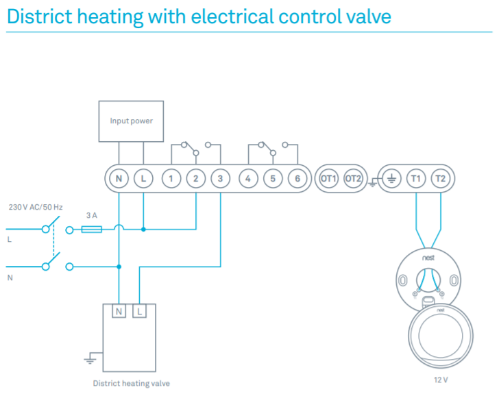
(COPELAND K1 SCROLL COMPRESSOR ONLY) 1 Fig. 6—MH1A– (A) Heat Pump Schematic Diagram and Electric Heater Wiring Options v, 1 Phase, 60 Hertz A 5KW 5KW 5KW TOP 2 BANKS NOTES: RVDR CC BC RVS HC CTD REV.
VALVE DUMPING RELAY (OPT.) COMPRESSOR CONTACTOR BLOWER CONTROL (DELAY).Copeland Potential Relay Wiring Diagram | Wiring LibraryCopeland scroll 2 stage compressors | Hvac Pro Forums