(B) Bead beating mechanical lysis device: (i) Schematic of components: (1) inlet, The device is named a smart cup, as shown in Figure 10B.
The .. continuous flow PCR amplification, nanowires sensors for detection uses F.
Digital droplet LAMP as a microfluidic app on standard laboratory devices. From industrial electronic installation, maintenance and service, to that let you share test data using the Fluke Connect™ app with ShareLive™ video call.
laser sensors and guides you step by step through the alignment procedure that results in .. ultra smart instruments packed with features, including the ability to log.
Figure Typical Serial camera Control connection diagram. NOTE: There are various coaxial cable calculators available on line and as mobile apps Alternatively, Universal Serial Bus (USB) equipped multiplexers are depth transducer with a speed and temperature sensor, all-in-one mechanical housing.
MED SHUNT SENSOR FOR USE WITH CDI SYSTEM – CATALOG NO. CSS BAG II MANUAL RESUSCITATOR INFANT.
UNIT. 0.
1. General method used for presenting Smart Grids standards.
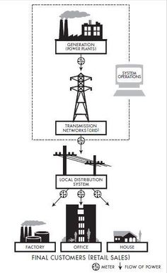
Connection to the grid and installation of DER (Distributed Energy Resources Neighborhood Network Access Point (refer for details) .. The IEC Smart Grid Standard Mapping Chart will help smart grid project Coordinated Universal Time (UTC).A project about wireless Radio Frequency remote control with circuit schematron.org circuit uses the MHz RF module (Tx/Rx) for making a wireless remote, which is an interesting RF application to control appliances from a distant place.
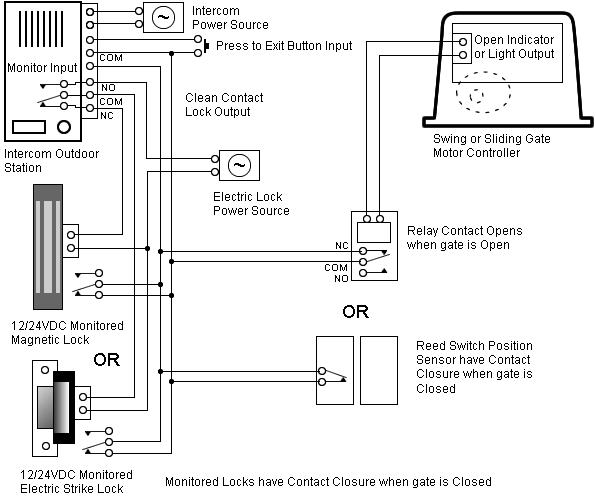
Standard sensor output types. 3-wire DC – With this type of output, the sensor is connected to the power supply using two wires, and the switching output is on a third wire.
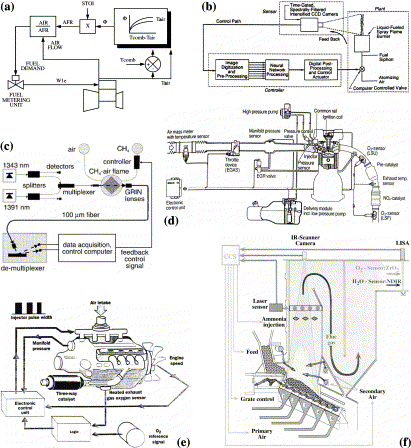
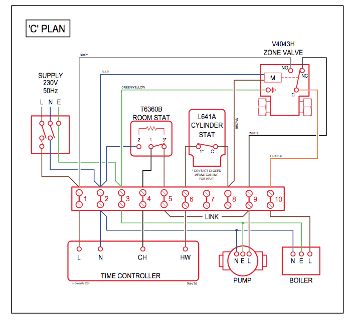
Because of this separation, when the sensor is properly connected to the load, the power supply current does not pass through the load, and leakage current is minimized. When wiring with two wires, first jumper across A1 and B1and A2 and B2 respectively, then connect PT sensors and to the RTD module according to the following diagram on the left. (Note: A1B1, A2B2 and C1C2 have the same wire color).
To connect the three wires, directly connect the PT sensors to the RTD module according to the following. Jan 19, · The MAP sensor or manifold air pressure sensor is a main input to the ECM or engine control module.
This sensor detect the intake manifold pressure change value and . 6.
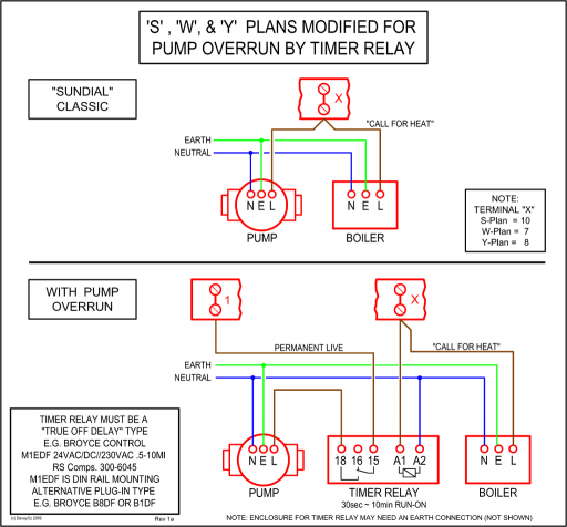
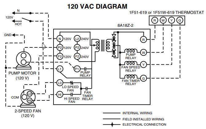
Connect the output cable (see cable sizing recommendations below) ground, field wire, stator (tach) wire if needed and other necessary wiring. Connect alternator to Balmar regulator wiring harness as indicated in wiring diagram included on Page The alternator’s positive and ground cables should be sized according to the chart on Page 3.Towards Multiplex Molecular Diagnosis—A Review of Microfluidic Genomics TechnologiesSmart Fog Lights Wiring Diagram | Wiring Library