
An AC power supply schematic symbol represents an alternating current (AC) power source in electronic circuit diagrams. It is a graphical representation of the power source that provides electrical energy in the form of a sinusoidal voltage waveform. The AC power supply symbol is commonly used in electrical and electronic engineering to represent the main power input or output of a circuit or device.
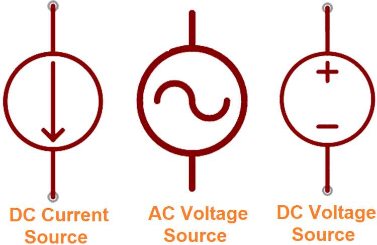
The AC power supply symbol consists of a circle with a sine wave inside, denoting the alternating current nature of the power source. The circle represents the connection point for the power supply, while the sine wave represents the varying voltage magnitude and polarity over time. This symbol allows designers and technicians to easily identify and differentiate AC power sources from other types of power sources, such as DC power supplies or batteries.
Understanding and accurately interpreting AC power supply schematic symbols is essential for designing and troubleshooting electronic circuits. By using this symbol, engineers and technicians can easily determine the power input or output connections of a circuit, ensuring the correct implementation and functioning of the circuit. Additionally, this symbol helps in identifying potential issues or faults related to the power supply, aiding in the troubleshooting process.
AC Power Supply Schematic Symbol

An AC power supply schematic symbol is a graphical representation used in electrical circuit diagrams to represent an alternating current (AC) power source. The symbol typically consists of a circle with a straight line inside, representing the two terminals of the power source. On the line, there may be small perpendicular lines or waves to indicate the alternating nature of the current.
The AC power supply schematic symbol is commonly used in various types of circuits, including those found in electronic devices, power distribution systems, and industrial equipment. It serves as a visual representation of the power source and helps designers and technicians understand the circuitry and connections involved.
The symbol is important because it provides a standardized way of representing an AC power source, regardless of the specific voltage or frequency. It allows engineers and technicians to easily identify and differentiate between AC and other types of power sources, such as DC (direct current).
When working with AC power supply schematic symbols, it is essential to pay attention to the power rating, voltage, and frequency specifications of the actual power source being used. This information should be properly incorporated into the circuit diagram to ensure accurate representation and safe operation of the electrical system.
Understanding the importance of schematic symbols in electronic circuits
Schematic symbols are an essential part of electronic circuits as they provide a standardized and concise representation of the components used in a circuit. These symbols allow engineers and technicians to easily understand and analyze the circuit design. Without schematic symbols, it would be challenging to communicate and interpret circuit designs accurately.
AC power supply schematic symbol is one such symbol that plays a crucial role in electronic circuits. It represents a source of alternating current (AC) in a circuit. The symbol typically consists of a sine wave with an arrow indicating the direction of current flow. Understanding this symbol is essential for correctly identifying and interpreting the AC power supply component in a circuit.
The importance of schematic symbols extends beyond just identifying components. They also provide information about the characteristics and properties of the components. For example, resistor symbols indicate its resistance value, capacitor symbols indicate its capacitance value, and so on. This allows engineers to make informed decisions about the selection and placement of components in a circuit.
Moreover, schematic symbols help in troubleshooting and repairing electronic circuits. By referring to the schematic diagram, technicians can easily locate and identify faulty components or connections. They can also quickly understand the interconnections between different components, making the troubleshooting process more efficient.
In summary, schematic symbols play a vital role in electronic circuits by providing a standardized representation of components and facilitating communication, analysis, and troubleshooting. Understanding and correctly interpreting these symbols is crucial for engineers and technicians involved in the design, testing, and maintenance of electronic circuits.
Overview of AC Power Supply Schematic Symbols
An AC power supply is an essential component in electronic circuits, providing the required electrical energy to power various devices. In circuit diagrams, AC power supply schematic symbols are used to represent different types of power supplies and their characteristics.
1. AC Power Source: The symbol for an AC power source represents the alternating current provided by the electrical grid. It is typically represented by a sine wave with labeled values for voltage (V) and frequency (f).
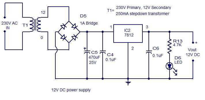
2. Transformer: A transformer is a vital component in an AC power supply circuit. It is used to step up or step down voltage levels as required. The schematic symbol for a transformer consists of two coils, usually labeled with the number of turns, and a corresponding dot indicating the polarity.
3. Rectifier: The rectifier symbol represents a circuit element that converts AC voltage into DC voltage. It usually consists of a series of diodes placed in a specific configuration to allow the flow of current in only one direction.
4. Capacitor: Capacitors are used in AC power supply circuits to store and release electrical charge. The capacitor symbol in a schematic diagram is represented by two parallel lines, with one plate labeled positive (+) and the other negative (-).
5. Inductor: Inductors are devices used to store energy in the form of a magnetic field. In AC power supply circuits, inductors are often used for filtering purposes. The inductor schematic symbol consists of a coil of wire, usually wrapped around a magnetic core.
6. Voltage Regulator: Voltage regulators are essential for maintaining a constant voltage output from an AC power supply. The schematic symbol for a voltage regulator typically consists of a triangle, with an input and output terminal indicated.
Overall, these AC power supply schematic symbols are crucial for understanding and designing electronic circuits that rely on a stable and regulated power source. Familiarity with these symbols enables engineers and technicians to interpret circuit diagrams accurately and troubleshoot power supply-related issues effectively.
The significance of AC power supply symbols in circuit design
In circuit design, AC power supply symbols play a crucial role in representing and understanding the power source used in a circuit. They provide essential information about the type of power being used, allowing designers and technicians to properly analyze, troubleshoot, and design electrical systems.
The AC power supply symbol, commonly represented as a sine wave, indicates that the circuit is being powered by an alternating current source. It provides information about the voltage waveform, frequency, and phase of the power source. This symbol helps engineers identify the power characteristics of a circuit and ensure compatibility with other components and devices.
The sine wave symbol: The sine wave symbol for AC power supply represents the periodic nature of the alternating current, showing how the voltage varies over time. It is an important visual representation that aids in understanding the behavior of the power source and its impact on the rest of the circuit.
Voltage and frequency: The AC power supply symbol also provides information about the voltage level and frequency of the power source. This information is important in determining the power requirements of the circuit and selecting appropriate components. Voltage and frequency compatibility is crucial for proper circuit operation and safety.
Phase: The AC power supply symbol may also indicate the phase of the power source. Phase refers to the timing relationship between multiple AC waveforms. This information is vital in certain applications where synchronized operation or specific phase relationships are required.
Compatibility and safety considerations: By using AC power supply symbols, engineers can ensure proper compatibility between different elements of a circuit. They can identify potential issues such as voltage mismatches or frequency conflicts that can cause malfunction or damage. Additionally, understanding the AC power supply symbol helps ensure safe operation, preventing electrical hazards and reducing the risk of electrical accidents.
In summary, AC power supply symbols are essential in circuit design as they provide vital information about the power source used. They help engineers understand the voltage waveform, frequency, and phase of the power supply, ensuring compatibility, safety, and optimal circuit performance.
Commonly used AC power supply schematic symbols
An AC power supply is an essential component in many electronic circuits, providing the necessary voltage and current to operate various devices. In schematic diagrams, specific symbols are used to represent different components of an AC power supply system. Understanding these symbols is crucial for engineers and technicians working with electrical circuits.
Here are some commonly used AC power supply schematic symbols:
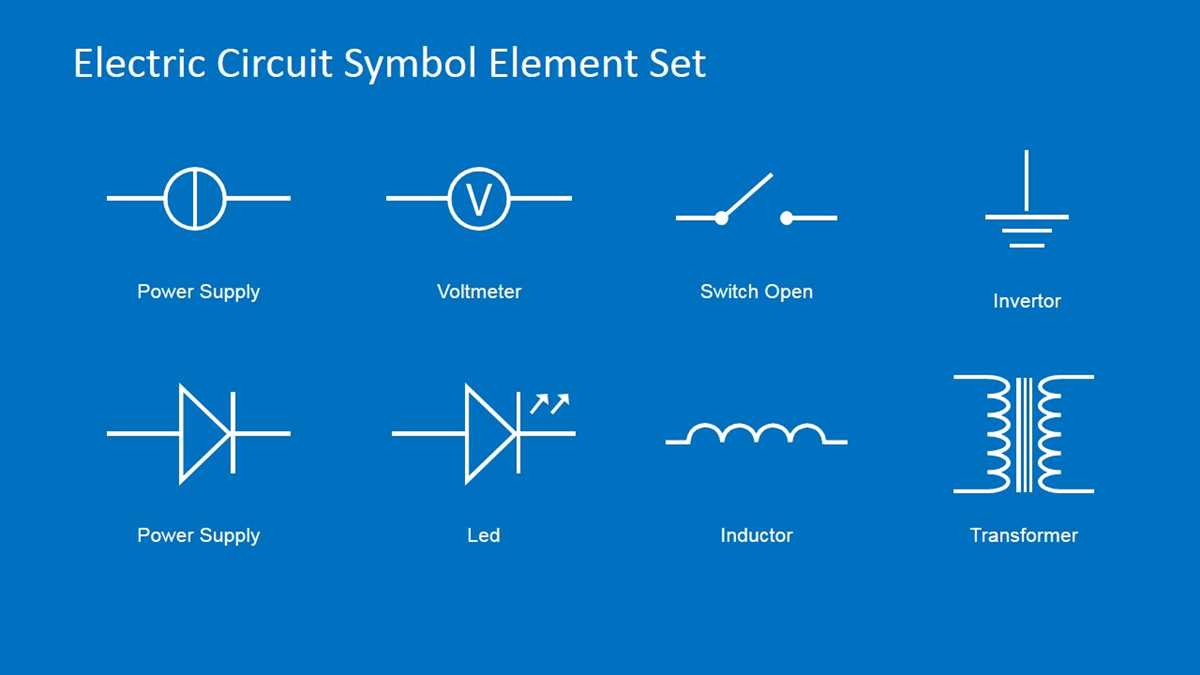
- Transformer: Represented by a coil symbol with a varying number of windings, the transformer is used to step up or step down the incoming AC voltage to the desired level.
- Rectifier: Shown as a diode symbol or a combination of diode symbols, the rectifier is responsible for converting AC voltage into DC voltage by allowing current to flow in one direction only.
- Filter capacitor: Illustrated as two parallel lines with curved ends, the filter capacitor is used to smooth out the rectified DC voltage by storing and releasing electrical energy.
- Voltage regulator: Depicted as a symbol with a horizontal output line and a reference line, the voltage regulator ensures a constant output voltage despite variations in the input voltage and load.
- Fuse: Represented by a squiggly line with two parallel lines, the fuse acts as a protective device by interrupting the circuit in case of excessive current flow, preventing damage to other components.
- Switch: Usually denoted by a line with a diagonal line crossing it, the switch controls the flow of AC power to the circuit, allowing it to be turned on or off.
These are just a few examples of the AC power supply schematic symbols commonly used in electronic circuits. By understanding and correctly interpreting these symbols, engineers and technicians can design and troubleshoot AC power supply systems effectively.
Interpreting AC Power Supply Schematic Symbols in Circuit Diagrams: Summary
In circuit diagrams, AC power supply schematic symbols are commonly used to represent various components and elements related to AC power supply. Understanding these symbols is essential for interpreting and analyzing circuit diagrams, as well as designing and troubleshooting electrical systems.
AC Power Supply Symbol:
The AC power supply symbol typically consists of a line with a sinusoidal wave symbol (represents AC voltage) and two perpendicular lines (represents connections to the power source). This symbol indicates the presence of an alternating current power source.
Components and Elements:
In circuit diagrams, there are several components and elements related to AC power supply that are represented using specific symbols. These include resistors, capacitors, inductors, transformers, diodes, transistors, relays, switches, and more. Each of these components has its own unique symbol, which helps identify its purpose and role in the circuit.
Connections:
AC power supply schematic symbols also represent various connections and relationships between components. These connections include series connections (components connected in a line), parallel connections (components connected side by side), ground connections (often represented by a horizontal line with three short, vertical lines), and more.
Schematic Diagrams:
Schematic diagrams are graphical representations of circuits, where various symbols are used to represent components, connections, and relationships. These diagrams provide a clear and concise overview of the circuit’s structure and functionality, allowing engineers and technicians to understand and analyze the circuit design.
Interpreting Symbols:
When interpreting AC power supply schematic symbols, it’s important to refer to the corresponding legend or key that provides a description of each symbol used in the circuit diagram. This ensures accurate understanding and interpretation of the circuit diagram.
Overall, understanding and interpreting AC power supply schematic symbols is crucial for anyone working with electrical systems. Whether you are designing new circuits, troubleshooting existing ones, or analyzing complex electrical systems, having a solid understanding of these symbols enables effective communication and interpretation of circuit diagrams.