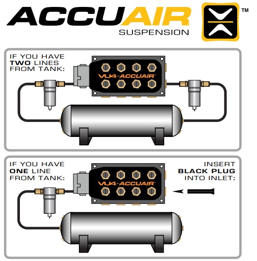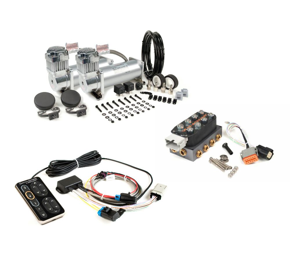
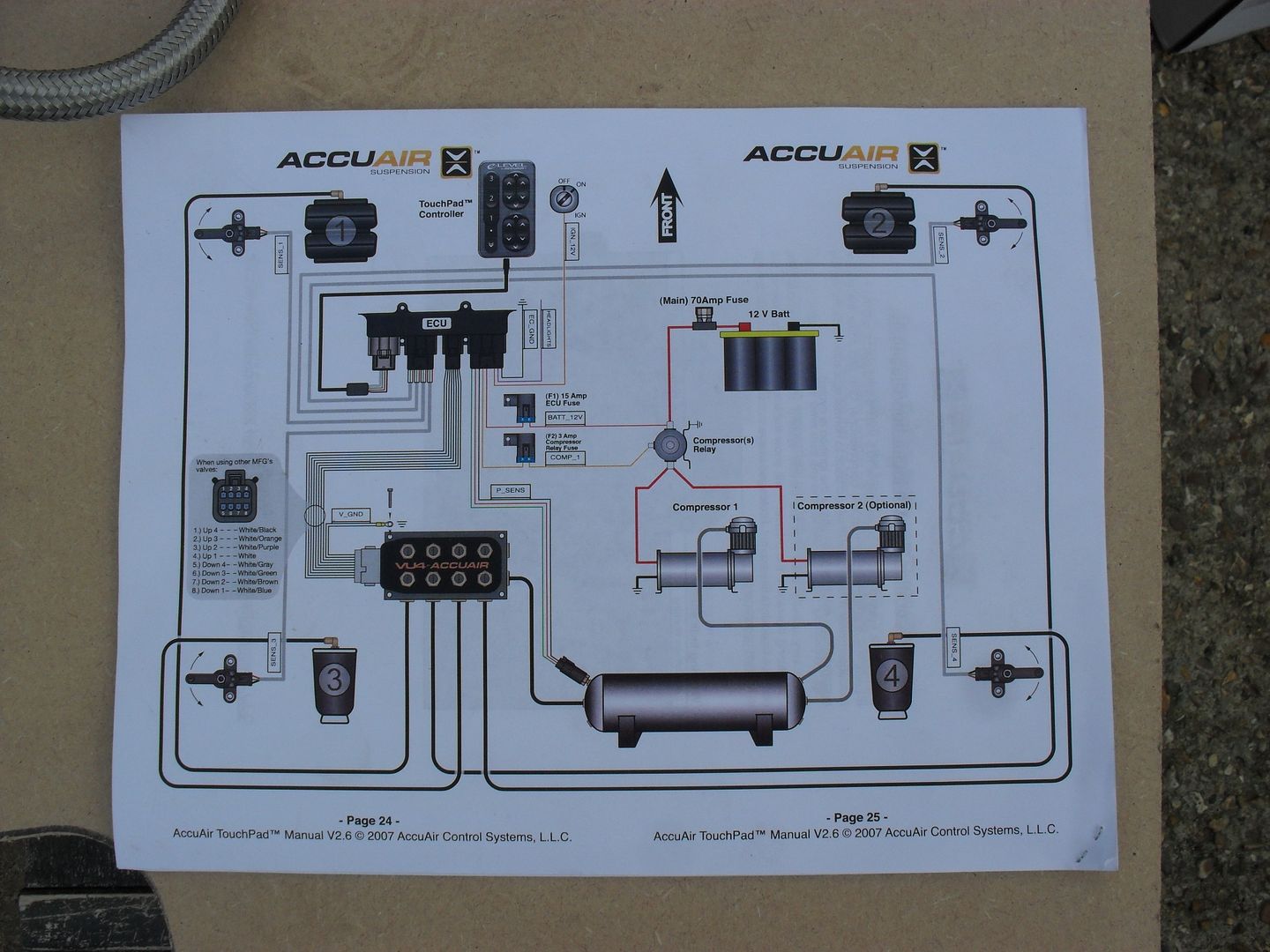
Note: If you have purchesed the plug and play AccuAir VU4 harness, 1) Reference the wiring diagram on page 1 to connect the TouchBox valve control wires.
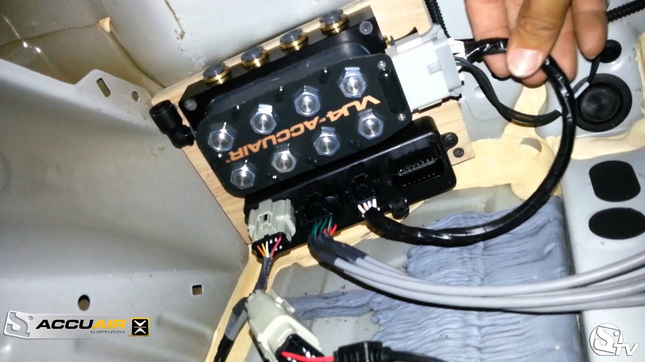
With AccuAir’s previous install record including the likes of James Hetfield’s and provided a custom floating mount for the ECU and VU4. AVS VALVE WIRING HARNESS 10′, 15′, 20′ – ACCUAIR VU4 VALVE TO AVS 7- SWITCH BOX AVS brand, plug and go wiring harness.
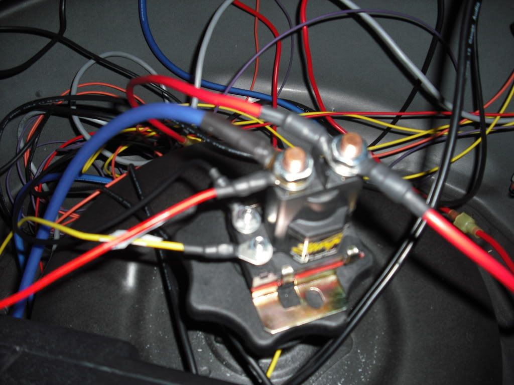
ability, the AccuAir e-Level™ also manages your Air Compressor(s) to keep onboard . Place the ground eyelet from the VU4 wiring harness under one of the cap- The following diagrams illustrate both “Standard” and “Optional” mounting.
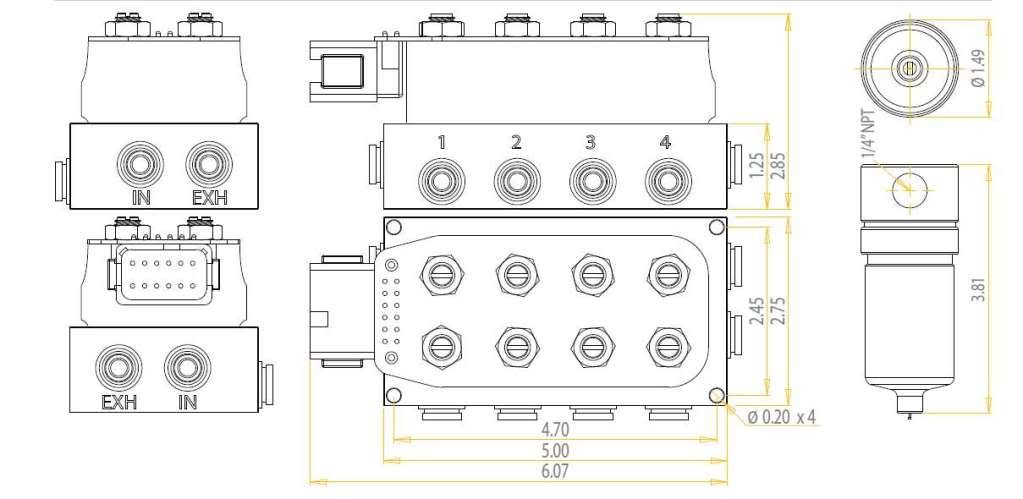
Valve Connector (Gray). Gray 1 – Up Solenoid 2.
Gray 2 – Up Solenoid 3. Gray 3 – Up Solenoid 4.
Gray 4 – Down Solenoid 4. Gray 5 – Down Solenoid 3.Wiring Diagram Installation Overview ACCUAIR will repair or replace any failed components for the life of the vehicle given that the components were installed and operated as intended by ACCUAIR.
Upon the return of a failed component(s), ACCUAIR will determine Place the ground eyelet from the VU4 wiring harness under one of the. Plug and go wiring harness.
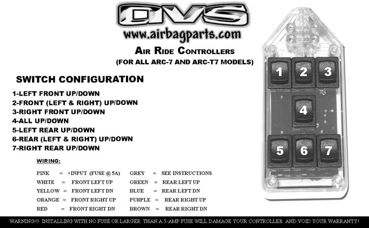
Plugs directly into any AVS 7 switch box and AccuAir’s VU4 manifold valve. Also includes accessory wire to provide switched power to your compressor’s relays/solenoids.
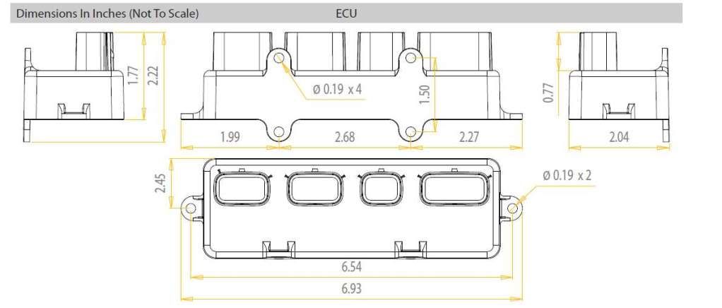
Remote fill and dump wires for your AVS ARC-7 switch box are also included in the harness. AVS VALVE WIRING HARNESS 10′, 15′, 20′ – ACCUAIR VU4 VALVE TO AVS 7-SWITCH BOX AVS brand, plug and go wiring harness.
Plugs directly into any AVS ARC-7 or AVS ARC-T7 switchbox and Accuair’s VU4 manifold valve. Also includes accessory wire to provide switched power to your compressor’s relays/solenoids.5/5. AccuAir TouchPad™ Controller Installation Manual V AccuAir Control Systems, L.L.C.
Table Of Contents Terms & Conditions System Diagram Test Mechanical & Height Sensor Installation Mounting & Wiring Installation Installation Overview Page Page Page Page 18 Page Page 30 Page Electrical Hookup Setup Programming. ENDO Instructions V Page 1 AccuAir Suspension FOR AND AIR PRESSURE LIMITS Both ENDO-T and ENDO-VT are DOT rated for psi maximum pressure ( bar).Failure to observe maximum rated pressure could result in tank rupture and consequent property damage or personal injury.SS Instal Wiring Diagram (V)schematron.org – Looking for accuair vu4 & Avs switchbox diagrams
