
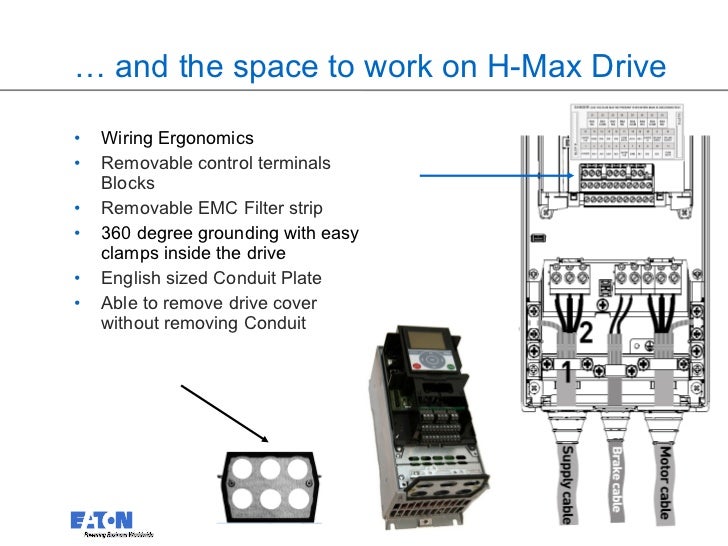
ACHPCR/PDR Packaged Drives with Disconnect (1 HP) When installing input power and motor wiring, refer to the following, as appropriate: The following diagram shows the power and ground terminal layout for frame sizes.
With drives ranging from 1 to HP, the ACH series features a universal full See the attached sample wiring diagram for further details. ACH Product Bulletin | 1.
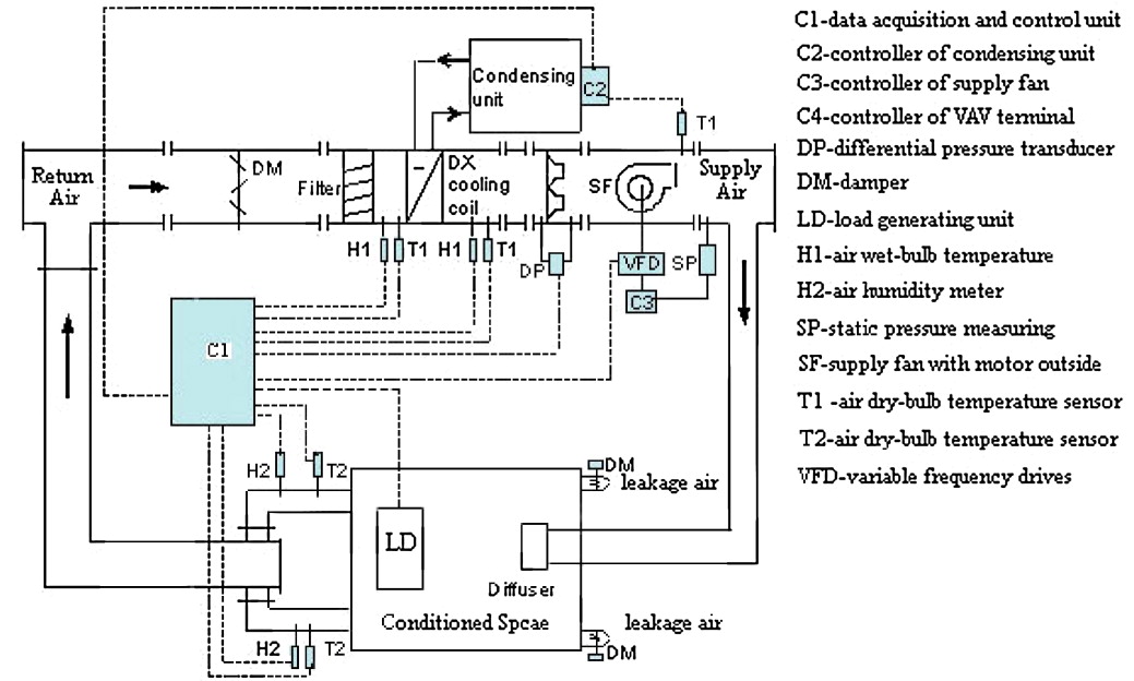
ACH control circuit connection diagram for each macro. ..
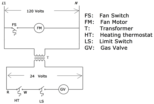
sense the problem and display an OUTPUT WIRING fault. The reader is expected to know the fundamentals of electricity, wiring, electrical components and electrical schematic symbols.
schematron.org Page 7 Friday, . ACH Installation, Operation and Maintenance Manual.
Safety. Safety ..
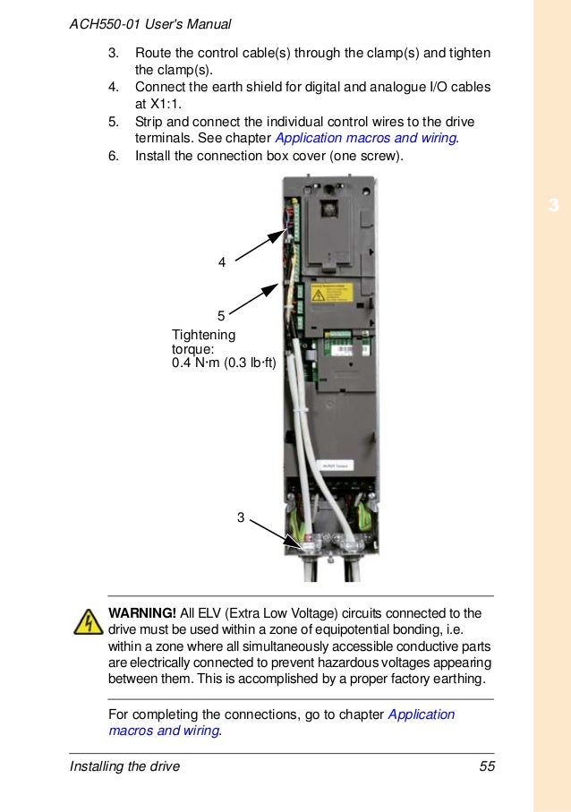
The locations of screws EM1 and EM3 are shown in the diagram on page 8. The locations . Strip and connect the individual control wires to the drive terminals.
Danish, German, English, Spanish, Finnish, French, Italian, Dutch, Portuguese, Russian, Swedish – 0,38MB. ACH User’s Manual 3AFE (English) ACH User’s Manual 3AFE (English) ACHUH User’s Manual 3AUA (English) • Safety • Installation Application macros and wiring 6. Real-time clock and timed functions 7.
Serial communications 8. Parameter listing and descriptions 9.
Diagnostics and maintenance The following is a typical power diagram. Installation Flow Chart The installation of Classic Bypass Configurations for ACH drives follows the The following figures show the wiring connection points.
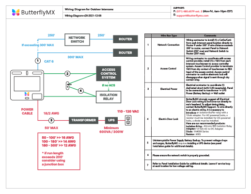
Refer to the ACHUH User’s Manual for control connections to the drive. ABB ACH Installation Manual.
Bacnet/ip router module rbip Hide thumbs. Also See for ACH User The wiring starts with the ACH drive (the first end of the segment), continues in the drive to the router module and then to the next stations on the MS/TP segment. The ACH provides proven reliability, flexibility, and every essential HVAC communication protocol.
It is pre-programmed for several applications, including: .Abb Drive Ach Wiring Diagram | Wiring LibraryABB ACH INSTALLATION MANUAL Pdf Download.