Ensure your system operates efficiently by following a reliable setup for connecting auxiliary cooling units. Start by identifying the power source for the motor and confirming its compatibility with the voltage requirements of the new unit. You’ll need a robust relay to handle the electrical load, positioned between the switch and the power source to ensure a clean current flow.
Connect the control switch to the system, making sure it’s capable of handling the required amperage. A manual or automatic switch can be used, but ensure it’s placed in a convenient location for easy operation. Integrate a temperature sensor if automatic control is desired, positioning it in an area that accurately detects the system’s temperature without interference from other components.
Double-check all grounds and ensure solid connections to prevent electrical issues. Use heat-resistant wiring for all connections, particularly those exposed to high temperatures. For optimal performance, consider using fuses or circuit breakers to protect the system from potential overloads.
Finally, test the entire configuration before full operation. Run the system through a few cycles to make sure the control switch, relay, and sensors are functioning as expected, ensuring safe and effective cooling in the long term.
Wiring Setup for Auxiliary Cooling System
To ensure proper operation of your auxiliary cooling system, follow these essential steps for a secure and reliable installation.
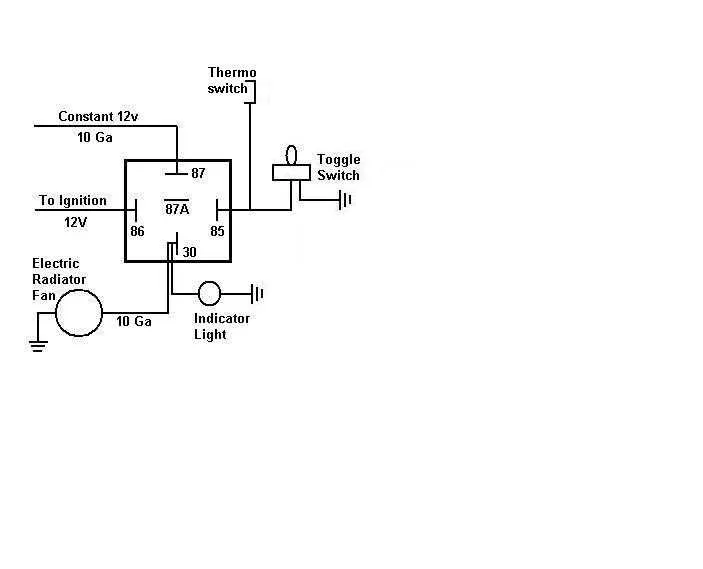
- Identify the power source: Choose a suitable power wire, preferably with a 12V constant feed, ensuring that the system can function properly even when the vehicle is off.
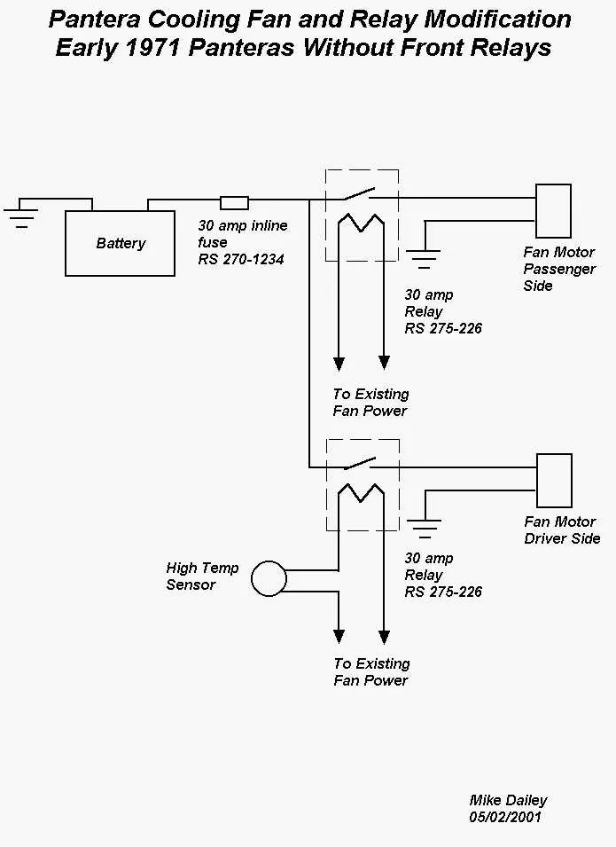
- Choose a reliable relay: Use a relay rated for the correct amperage of the cooling unit to prevent overheating or failure. A 30/40A relay is commonly used for most systems.
- Ground connection: Ensure that the ground wire is securely connected to the vehicle’s metal chassis to prevent any electrical issues.
- Connect the trigger wire: This wire is responsible for activating the relay. Typically, it connects to the vehicle’s thermostat switch or fan control sensor to engage the system at a certain temperature.
- Fuse protection: Install a fuse between the power supply and the relay. Use a fuse that is rated for the total current draw of your cooling unit to protect against electrical shorts.
After completing the connections, test the system by turning on the vehicle and ensuring that the auxiliary unit activates as expected at the correct temperature threshold.
- Verify the power connections by checking voltage at each point with a multimeter.
- Confirm relay activation by listening for a clicking sound when the system should engage.
- Double-check the wiring for any loose or exposed connections that could cause short circuits.
Correct installation is crucial for the efficiency and longevity of your auxiliary cooling system, and ensuring every wire is in its proper place will save you from future complications.
Choosing the Right Wire Gauge for Cooling System Installations
Select a wire gauge that can handle the amperage draw of the unit without excessive voltage drop or overheating. For most medium-sized systems, use 12 AWG wire, as it supports up to 20 amps, which is sufficient for typical setups. If your setup requires more current, such as heavy-duty models, opt for 10 AWG wire, which can safely handle up to 30 amps.
The wire length is another important factor. For every additional foot of wire, the voltage drop increases. For installations longer than 10 feet, consider upgrading to a lower gauge wire to maintain optimal performance and prevent power loss.
Always verify the fuse or circuit breaker rating to match the wire gauge. A fuse rated for the wire gauge ensures protection against overloads. For 12 AWG wire, a 20-amp fuse is appropriate, while 10 AWG would require a 30-amp fuse.
Thicker wires provide lower resistance, but using excessively thick wire can be cumbersome and harder to work with. Balance between wire thickness and the specific power requirements for the best performance and ease of installation.
Step-by-Step Guide to Wiring an Auxiliary Cooling System
Start by selecting the correct relay and fuse for your setup based on the power rating of the cooling unit. Choose a relay that matches the amperage draw, typically around 30 to 40 amps, and use a 30-amp fuse for safety. This prevents overloading the electrical system.
Next, locate a suitable location for mounting the cooling device. Ensure that the wires leading to it won’t be exposed to high heat or moving parts. Install a good-quality switch that will allow you to activate the system manually or wire it to the engine’s temperature sensor for automatic operation.
For the power supply, run a positive wire directly from the battery’s positive terminal, using a fuse holder near the battery to protect the circuit. Secure the wire using appropriate grommets if passing through the firewall to prevent wear.
Connect the other side of the relay to the positive terminal of the cooling unit. The ground connection should be made to a clean, solid chassis point to ensure a proper ground and prevent electrical noise.
For control, use a temperature sensor that will trigger the relay when the engine reaches a pre-set temperature. Wire the sensor to the relay’s trigger input. If opting for a manual switch, run a wire from the switch to the relay’s trigger terminal.
Double-check all connections, ensuring no exposed wires or potential shorts. Test the circuit by starting the engine and verifying that the system operates as expected. Make any necessary adjustments to the wiring layout for optimal performance.
Common Wiring Mistakes and How to Avoid Them in Aftermarket Fans

Always use the correct gauge wire for the system’s amperage. Undersized wiring causes heat buildup and potential damage to components. Refer to the fan’s specifications to select the appropriate wire thickness, usually listed in the product manual.
Improper grounding is another common issue. A weak or poorly connected ground can result in electrical noise, erratic performance, and possible failure. Ensure the ground wire is securely attached to a clean, bare metal surface free from rust or paint.
Incorrect relay installation can prevent the system from functioning properly. Always double-check relay wiring to ensure it’s connected to the right pins, as a miswiring can cause the fan to run intermittently or not turn on at all.
Don’t neglect fuse protection. Fuses are critical for preventing overcurrent damage. Install the correct fuse rating based on the fan’s draw. A fuse with a lower rating can blow prematurely, while a higher rating may not protect the circuit effectively.
Using spade connectors in high-vibration environments can cause loose connections over time. Solder the connections whenever possible, or use high-quality crimp connectors to ensure a secure and long-lasting bond.
Make sure to route the wires away from heat sources and moving parts. Exposure to excessive heat can degrade insulation, while friction with moving components can cause shorts or damage.
Lastly, always verify the wiring polarity when connecting the system to the power source. Reversing the positive and negative leads can damage sensitive components like control modules or switches.