When assembling or troubleshooting the electrical setup for your machine, it’s crucial to identify each component’s specific connection. Start by locating the power input terminals, which will be the central part of the assembly process. Ensure that the connections are secure and adhere to the manufacturer’s recommended voltage specifications to prevent potential electrical failures.
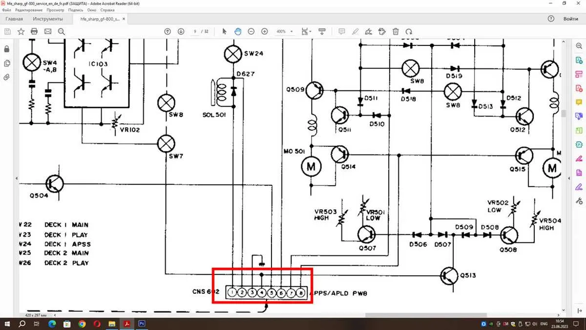
Next, focus on identifying the main circuit paths. These paths direct the current to various operational parts of the system, such as the motor and control board. For clarity, follow the labeled pins or connectors that are typically marked for ease of identification. Pay close attention to the ground connections, as improper grounding can lead to short circuits or inefficient power use.
For optimal performance, ensure the internal wiring routes do not interfere with moving parts. Additionally, always cross-check connections against the unit’s technical specifications to confirm they align with the required configuration. If discrepancies are found, refer to the component manual to rectify them promptly.
Safety Note: Always disconnect the power supply before working on any electrical components. Make sure you are using the correct wire gauges and connectors as outlined in the equipment documentation to avoid overheating or electrical hazards.
By carefully mapping out these connections and following standard procedures, you can significantly reduce the likelihood of errors and extend the lifespan of your equipment.
Electrical Connections Overview for Printer Model

Identify the power input terminals for the device. Ensure a proper connection between the power supply and the internal components. The main power line should connect to the designated input terminal, while the neutral wire should be routed to the designated ground point to avoid electrical hazards.
For the mainboard, pay attention to the communication ports. Properly connect the data cables to the control panel interface, making sure the cables are oriented correctly to avoid malfunctioning. The connectors should fit snugly, ensuring a stable data transfer.
Verify the connection to the motor. The motor terminals should be wired securely to the control unit, with the right polarity observed. Incorrect polarity can result in improper function or even damage to the system.
Ensure the safety switch is properly installed. This switch will prevent the machine from operating if not engaged. Check the wiring for any loose connections and ensure it’s properly seated in its mount.
Always check for short circuits before powering the system on. Inspect each cable for any signs of wear, and verify that none of the wires are in contact with other electrical parts. This will prevent unexpected faults during operation.
Testing phase: Once all connections are completed, carefully power on the device and observe the status lights. Any irregularities should prompt a review of the connections and the components involved.
How to Identify Power Supply Connections in a Copier

Start by locating the main power input terminals on the machine. These are typically found near the power switch or fuse area. Check the voltage specifications indicated on the unit or nearby labels for accurate voltage requirements.
- Look for a terminal marked with a “+” or “-” sign for DC connections.
- The AC power input is usually connected to a block with multiple pins; this often includes a grounding pin to ensure safety.
- Inspect any fuse or circuit breaker related to the power section; a blown fuse might indicate a power surge or malfunction.
When identifying wires, use a multimeter to confirm continuity between components. Follow these steps:
- Set the multimeter to measure resistance or continuity.
- Test each terminal by placing the probes on either side of the connections.
- If there’s continuity, it means the connection is properly established.
- Also, check for any signs of wear or burnt spots around the connections to avoid short circuits.
Pay attention to the polarity of connections. Reversing DC power lines can cause malfunction or permanent damage to the circuitry.
Understanding Printer Control and Signal Connections

Ensure accurate communication between components by following the precise layout of control and signal pins. The main control unit interfaces with various sensors and input devices, transmitting necessary data for operation. Always check the alignment of each wire to prevent incorrect connections that could lead to malfunctions.
To properly manage data flow, connect the signal pins in their designated slots. Data transfer occurs via dedicated lines, where signals should only be routed to specific terminals to avoid short circuits or miscommunication. Verify that the signal path adheres strictly to the pinout guide for the correct configuration.
Important considerations include ensuring that the ground connections are stable, preventing electrical interference. The power supply should be connected to the power input terminal with the proper voltage rating to ensure safe operation. Double-check that all signal paths are well-insulated to avoid accidental grounding or disruptions during active processes.
Regular testing of each connection is advised to identify potential issues with poor contacts or misrouted signals. If a malfunction occurs, use a multimeter to test continuity and voltage levels across terminals to verify each connection’s integrity.
Lastly, adhere strictly to the recommended layout and verify connections against the reference documentation to prevent operational failures.
Common Troubleshooting Tips for Electrical Connections

Check for any loose or disconnected terminals. Ensure all wires are securely attached and that no pins are bent or broken. Pay special attention to the power input connections, as these are often the source of interruptions.
Inspect for any visible signs of wear or damage on cables. Frayed wires or exposed metal can cause short circuits or prevent proper power distribution. Replace any damaged components immediately.
If the system is not powering up, verify the fuse and circuit breaker are in good condition. A blown fuse or tripped breaker can prevent electrical flow, so replace them if necessary and test the system again.
Test continuity with a multimeter. If continuity is lost at any point, trace the fault back through the system to isolate the exact location of the issue. This is crucial in identifying problems with specific connections or components.
Ensure the ground connection is intact. Poor grounding can lead to erratic performance or even system failure. Check for any loose grounding cables and secure them tightly.
Examine the power supply for fluctuations. Voltage instability can damage internal components. Use a stable power source and consider adding a surge protector if necessary.
For complex configurations, consult the connection map to verify the proper placement of each wire and component. Incorrect routing can cause malfunctions or prevent the system from functioning altogether.