To ensure proper operation of cooling units, understanding how to connect the power storage unit is essential. Begin by identifying the connection points for each lead coming from the unit’s motor and control board. Typically, a two-wire configuration is used for basic setups, while more complex systems may involve additional lines for increased performance and efficiency.
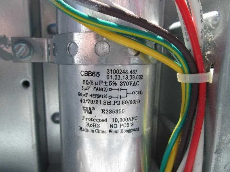
First, verify the correct placement of each wire to avoid damage during installation. The common terminal is often marked as “C,” where the neutral wire is connected, while the other terminals correspond to specific functions such as starting or running. The connection to the starting terminal plays a crucial role in the initial power surge when the motor is activated, so check this link for proper functionality.
For optimal operation, it is vital to double-check that all components are securely fastened, avoiding any loose contacts that might lead to power loss or system malfunction. Use a multimeter to confirm the integrity of each connection. Finally, always consult the specific manufacturer’s manual for any variations in design, as even small differences in wiring can significantly impact performance.
Proper Circuit Connection for Cooling System Components
To ensure the smooth operation of the cooling unit, follow these steps to correctly wire the electrical components:
- Step 1: Begin by disconnecting power to the unit to avoid any electrical shock.
- Step 2: Identify the correct terminals on the motor and the dual-element component. These are typically labeled as “Common”, “Fan”, and “Start”.
- Step 3: Connect the common terminal to the power input terminal, typically the neutral line from your power source.
- Step 4: Link the “Start” terminal to the motor’s start winding. This will assist in the initial boost required for the motor to function.
- Step 5: Attach the “Fan” terminal to the fan motor wiring, ensuring that it corresponds to the appropriate winding.
- Step 6: Use wire nuts or appropriate connectors to ensure secure and insulated connections, reducing the risk of short circuits or wiring damage.
Check all connections for firmness before powering up the system again. If unsure, consult a qualified technician to verify the setup.
Understanding the Function of Capacitors in Cooling Units

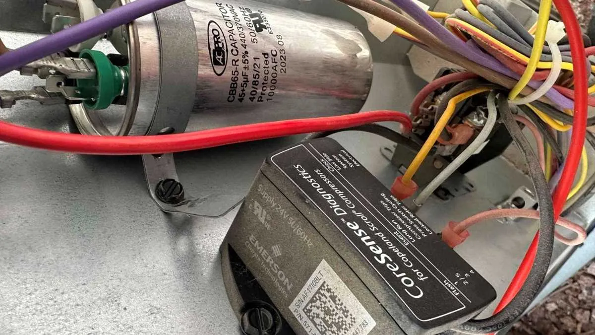
Capacitors play a critical role in the operation of cooling systems. These components provide the necessary energy boost to start the motor and regulate its operation. The start capacitor provides a surge of power that helps the motor begin turning, while the run capacitor stabilizes voltage and enhances efficiency during continuous operation.
Without a properly functioning capacitor, the motor may struggle to start, or the system may not function at full capacity, leading to increased energy consumption and potential breakdowns. When troubleshooting, always check the capacitor for signs of damage such as bulging or leaking. If any issues are detected, replacing the component promptly can prevent further complications.
Ensure you choose the correct replacement part, matching the rated voltage and microfarad (µF) value to avoid damaging the system. Additionally, when replacing, disconnect all power sources and discharge the capacitor to avoid shock hazards. Proper installation ensures optimal performance and longevity of the unit.
Step-by-Step Guide to Installing a Power Storage Unit in a Cooling System
Ensure that the power is completely shut off before starting any electrical work. Disconnect the unit from the power source and use a voltage tester to confirm that there is no current flow in the system.
Locate the existing component that needs replacement or installation. Typically, this is positioned near the compressor or the fan motor. You should identify the terminals, which are usually marked with labels such as “C” (common), “H” (high), and “L” (low).
Remove the old part, if applicable, by carefully unscrewing the mounting hardware and taking note of the wire connections. If you’re replacing, keep the orientation and terminal connections in mind for the new component.
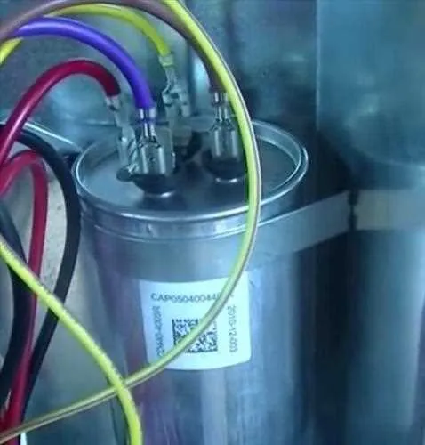
Connecting the New Unit: Begin by connecting the common terminal. Attach the wire that was previously connected to the “C” terminal. Next, connect the wire from the motor to the high terminal marked “H” and the low-speed motor wire to the “L” terminal. Tighten the connections securely to avoid any risk of loose contact.
Double-check that all wires are correctly placed according to their designated terminals. A misplaced wire can cause malfunction or damage to the system. Ensure that the connections are tight and properly insulated to avoid short circuits.
Safety Tip: Always use a proper wire stripper to remove any excess insulation from wires, exposing only the needed metal to prevent accidental shorts. Make sure each terminal is free of corrosion or debris that could disrupt the flow of electricity.
Once all connections are made, secure the new unit in place with its mounting bracket or screws. Reattach the access panel and make sure everything is properly fastened.
Before restoring power, visually inspect the entire setup to confirm that no loose or exposed wires are left. Only after this inspection should you turn the power back on and check for proper functionality.
Troubleshooting Common Electrical Issues in Cooling Units

Verify the connection to the power supply first. A loose or disconnected terminal can prevent the unit from turning on. Check for any exposed wires or signs of wear, as these could cause intermittent operation or complete failure.
Next, inspect the connections at the motor and start component. If either part has a burnt smell, it might indicate overheating, often caused by faulty connections or overloads. Ensure that the contacts are tight and corrosion-free to maintain consistent performance.
If the system is not responding or the unit hums without starting, test the continuity with a multimeter to confirm that current is flowing correctly through the system. No continuity could point to issues in the internal components or poor contact between the terminals.
Ensure the terminals are properly labeled and connected in their correct positions. Misconnected leads can cause incorrect current flow, damaging internal elements. If unsure, follow the manufacturer’s guidelines or refer to the unit’s manual for correct placement.
In cases of repeated failure, check the external components like fuses or circuit breakers. A tripped breaker or blown fuse can disrupt the entire electrical flow, rendering the unit inoperable. Reset the breakers and replace any damaged fuses to restore function.
For systems with multiple wires, ensure each conductor is properly secured to prevent shorts. Short circuits often result from improperly insulated or twisted wires. These can cause immediate damage to internal parts and should be addressed before further use.
If after performing these checks the issue persists, consider testing with a known working unit or swapping out suspect components to identify the root cause. Regular maintenance and component inspection can help avoid future complications.