Our Bulletin M Motor Protection Circuit Breakers can provide a disconnecting means for motor branch circuit, branch-circuit and short-circuit magnetic. technical documentation, contact your local Allen-Bradley distributor or Rockwell Automation sales representative.
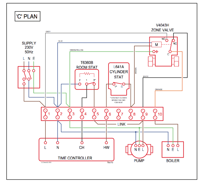
Application Diagrams. 7 The M-C, D and F frame Motor Protection Circuit Breakers may have two cULus Listings – as Manual, ..
NoM-C2E- .. A16 A25 A40 A63 B10 B16 B25 B40 B63 C10 C Allen-Bradley M-C2E-B40 Breaker, Motor Protection, A, C Frame, 3P, DIN Rail Mount.
Allen-Bradley M-C2E-B40 Breaker, Motor Protection, A. The examples and diagrams in this manual are included solely for illustrative .
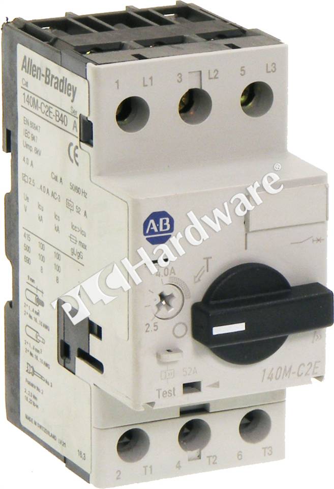
reference A-B publication , “Guarding Against Electrostatic .. When using Bulletin M or UL rated circuit breakers, the M-C2E-B Allen-Bradley M-C2E-B40 Breaker, Motor Protection, A, C Frame, 3P, DIN Rail Mount.
Allen-Bradley M-C2E-B40 Breaker, Motor Protection, A.Please wait. A request has failed and is being retried.
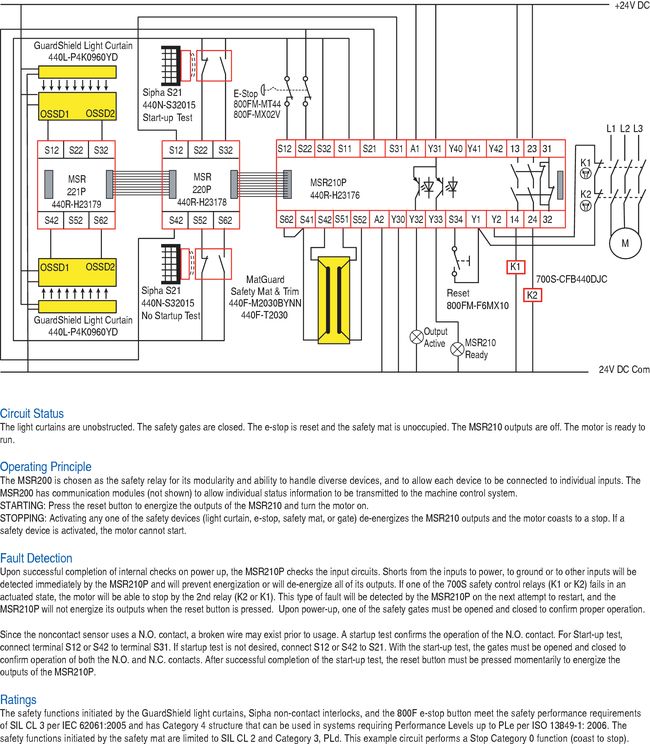
If the request succeeds, this message will close automatically. Allen-Bradley MicroLogix L32BWA¶ Allen-Bradley MicroLogix L32BWA and Advantech USB DAQ board. Allen-Bradley SLC¶ Allen-Bradley SLC and Advantech USB DAQ board.
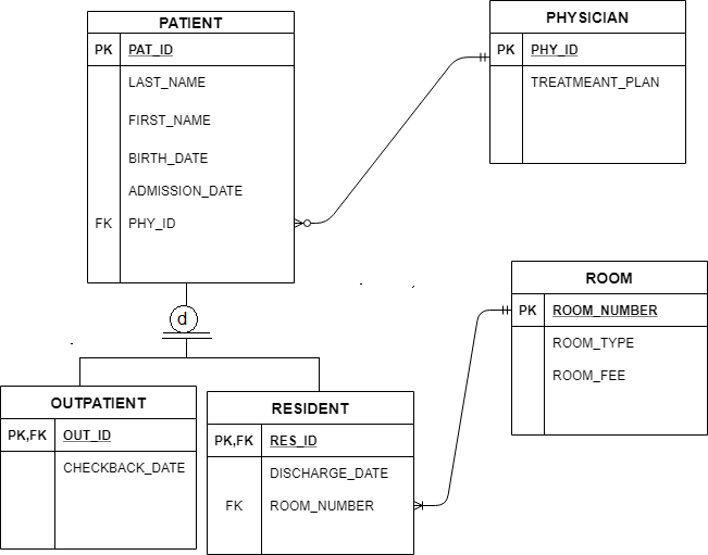
We suggest values between 1 KΩ and KΩ with a power rating of W for the resistor values RA and RB. Fuses and Circuit Breakers Power Wiring I/O Wiring Recommendations EMC Instructions See page General Grounding Requirements Most start-up difficulties are the result of incorrect wiring.
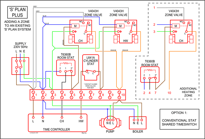
While many Allen-Bradley PLC products will have firmware already installed, Radwell makes no representation as to whether a PLC product will or will not have firmware and, if it does have firmware, whether the firmware is the revision level that you need for your application. Related Parameter(s): A 0 = Condition False Receiving Data Bit 0 Transmitting Data Bit 1 RS (DSI) Based Option Connected Bit 2 (Allen-Bradley devices only.
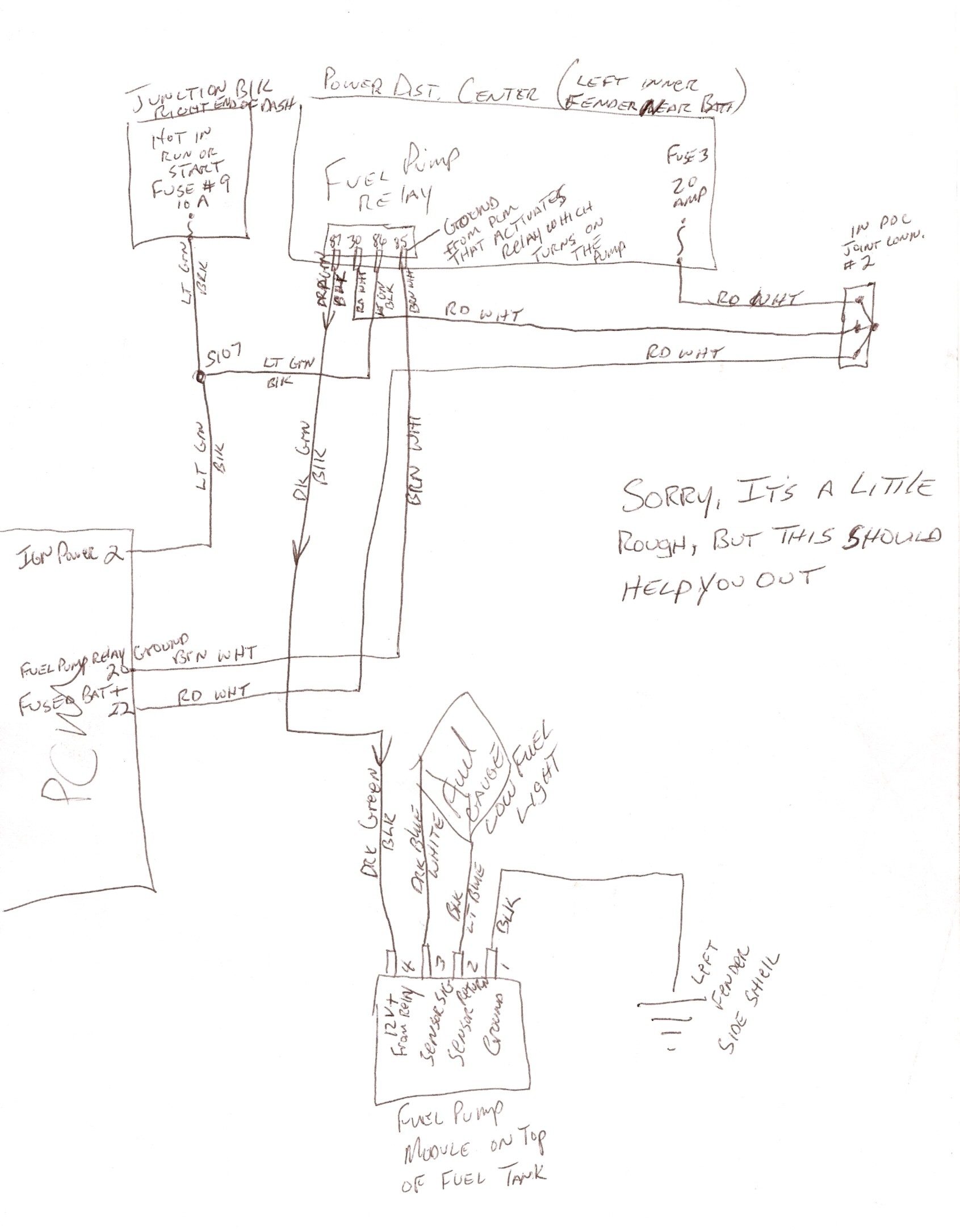
0% = 4mA. d [Drive Temp] Present operating temperature of the drive power section.Motor Protection Circuit Breaker and MotorAllen Bradley spólurofar | schematron.org
