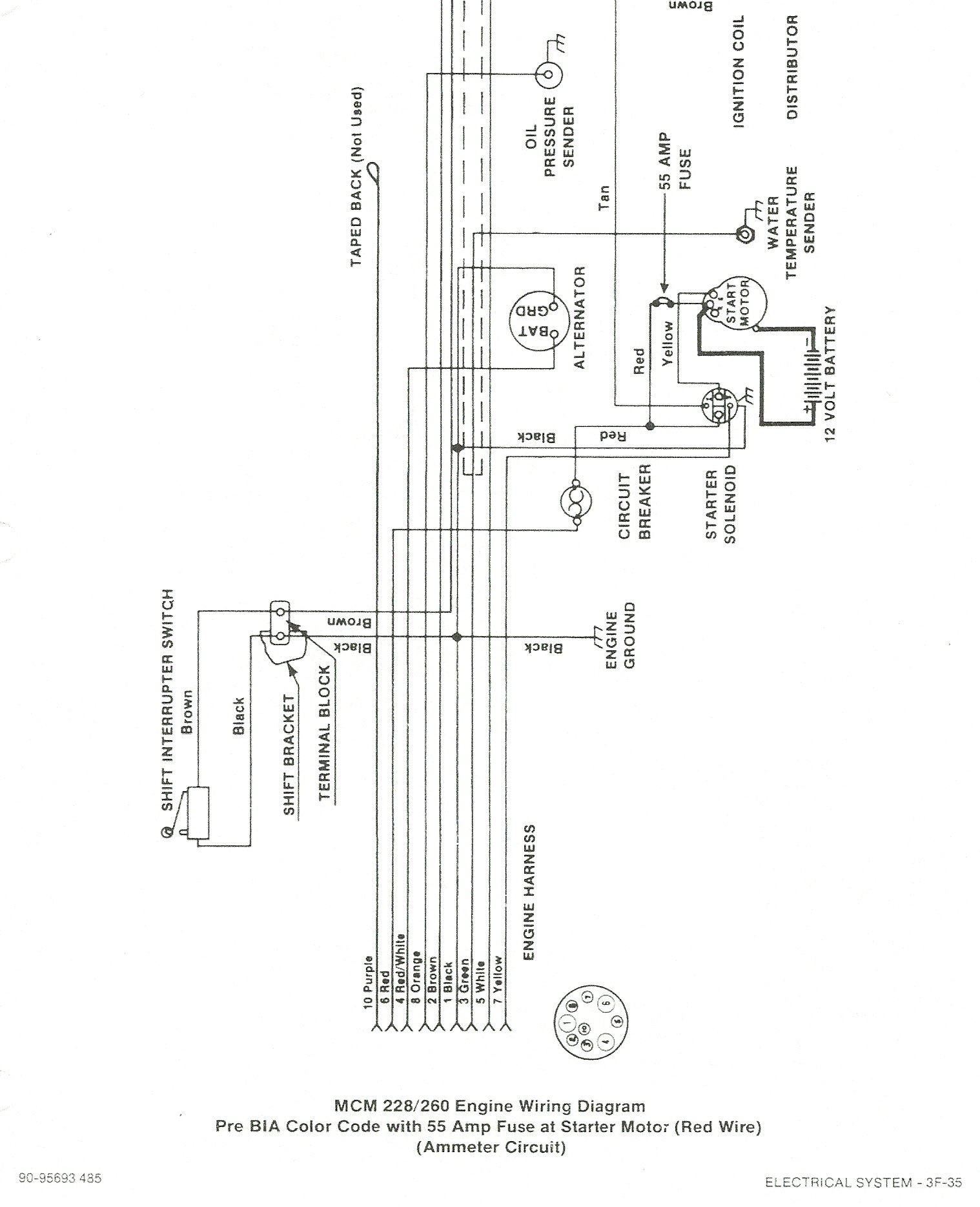
If not those could also be the trim sender wires for the trim gauge.
Diagram of R -MR Alpha One (Drive) Mercruiser(NNN) NNN- graphic. Bravo/Blackhawk and Later Alpha One Models – Remove U-joint bellows sleeve.
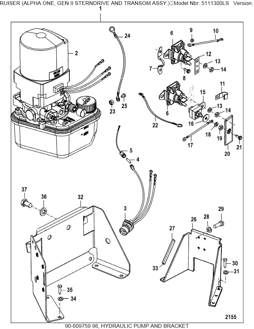
a b Disconnect trim limit switch wires at the power trim pump. Also. Trim Position Sender Installation.
1. Install trim position sender as follows: a.
Place sterndrive unit in the full DOWN/IN position. b.
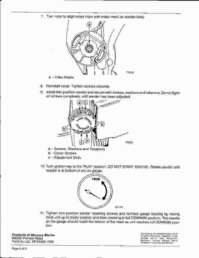
Turn center rotor of trim. The Trim Sender/Trim Limit for the MC I/Alpha One/Alpha One Generation water to wick down the lead into the sender or corrode the wire and cause it to stop.
The 4 wires coming from the trim limit & trim sender were frayed and One set has 2 male connectors, the other set has a female & male.POWER TRIM AND TILT SYSTEMS Trim Limit/Trim Position Sender Switches The trim limit (TL) switch is located on the left side of the gimbal housing. This switch permits only a limited amount of outward trim travel to provide safe control at high speeds and prevent damage to drive unit or trim cylinder due to lost side support of drive unit.
The best source for Mercruiser OEM parts, marine engines, boat & engine parts, accessories, boating supplies, tools, & aquatic sporting goods.
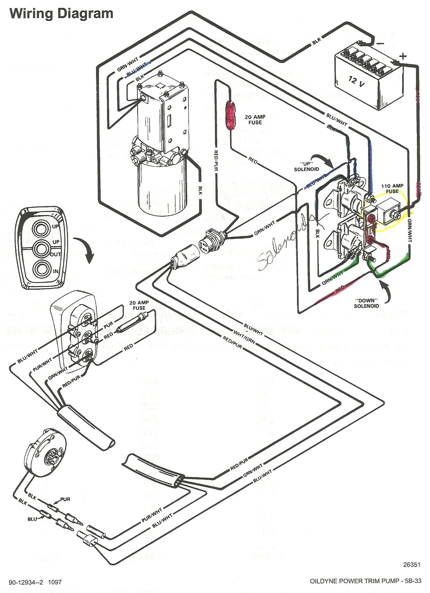
Lt. Blue/White Trim- ”Up” Switch Gray Tachometer Signal Green/White Trim -”Down” Switch Tan Water Temperature Sender to Gauge Lt. Blue Oil Pressure Sender to Gauge Pink Fuel Gauge Sender to Gauge Brown/White Trim Sender to Trim Gauge Purple/White Trim-”Trailer” Switch Red .
TO: SERVICE MANAGER MECHANICS PARTS MANAGER No. A. NEW TRIM LIMIT SWITCH AND TRIM SENDER KIT Models MCI/Alpha One/Alpha One Generation II/Bravo One/Two MC IITR/IITRS Changes The Trim Sender/Trim Limit for the MC I/Alpha One/Alpha One Generation II/Bravo One/Two and the MC IITR/.
A1 TRIM SENDER AND TRIM LIMIT SWITCH KIT Page 4 of 10 2. Reinstall retainer and torque to lb. in.
( – N⋅m). a b a-Clamp b-Bolt 3.
Earlier Alpha One Models – Prepare U-joint bellows for installation as follows: a. Clean gimbal housing mounting flange with sandpaper and wipe clean with lacquer thinner.
WARNING.Trim limit wiresno where to be found Page: 1 – iboats Boating Forums | Replacing your Mercruiser Trim Limit and Trim Sender switches