Volvo APADs Unit Mounted on Truck’s Firewall. Copyright Inputs and Outputs, Line diagram APADS Rules for Compressor Control CM (continued).
Hi there! Sorry to hear you are having trouble!
My name is ***** ***** I would like to try and help if I can! I need the last 8 digits of the vin number please?
I need. APAds® is a registered trademark of Index Sensors and Controls, Inc. Step 6.
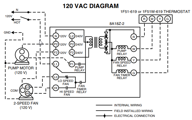
Installation of the APAds Control Module. Wiring Diagram. A/C Cab TStat On/Ofi Figure The inputs and outputs of a control module ( line diagram).
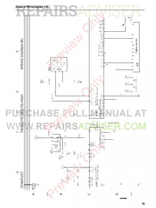
NC system with APAds ® (* _ Evaporator ~—/ 4BLowAPAds to the electrical contacts, allowing diagnostics of sensor, wiring, and connector faults. If anyone has a schematic or can help me out I would greatly The APADS turns the standard simple mack a/c wiring into a nightmare.2 volvo power The new series of Volvo D13 Power and efficiency for every application.
independent of the transmission clutch. FEATURES THAT IMPROVE PERFORMANCE. The APAds system will only operate with Index pressure switches designed for the APAds system.
They contain an internal resistor, which allows APAds to detect open wire faults. Without this resistor, other pressure switches appear as open or shorted wire faults to APAds.
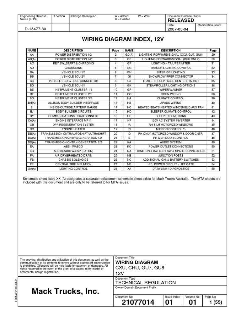
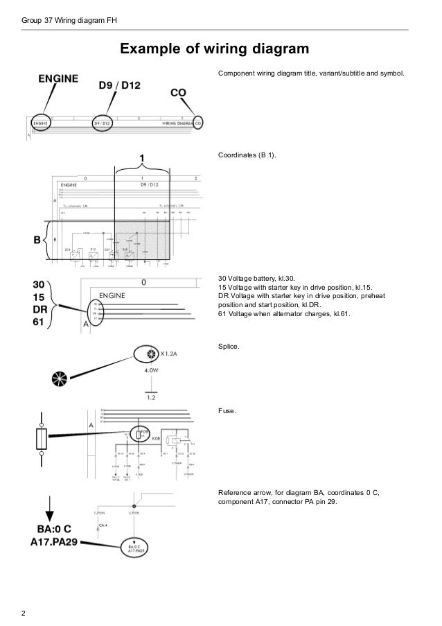
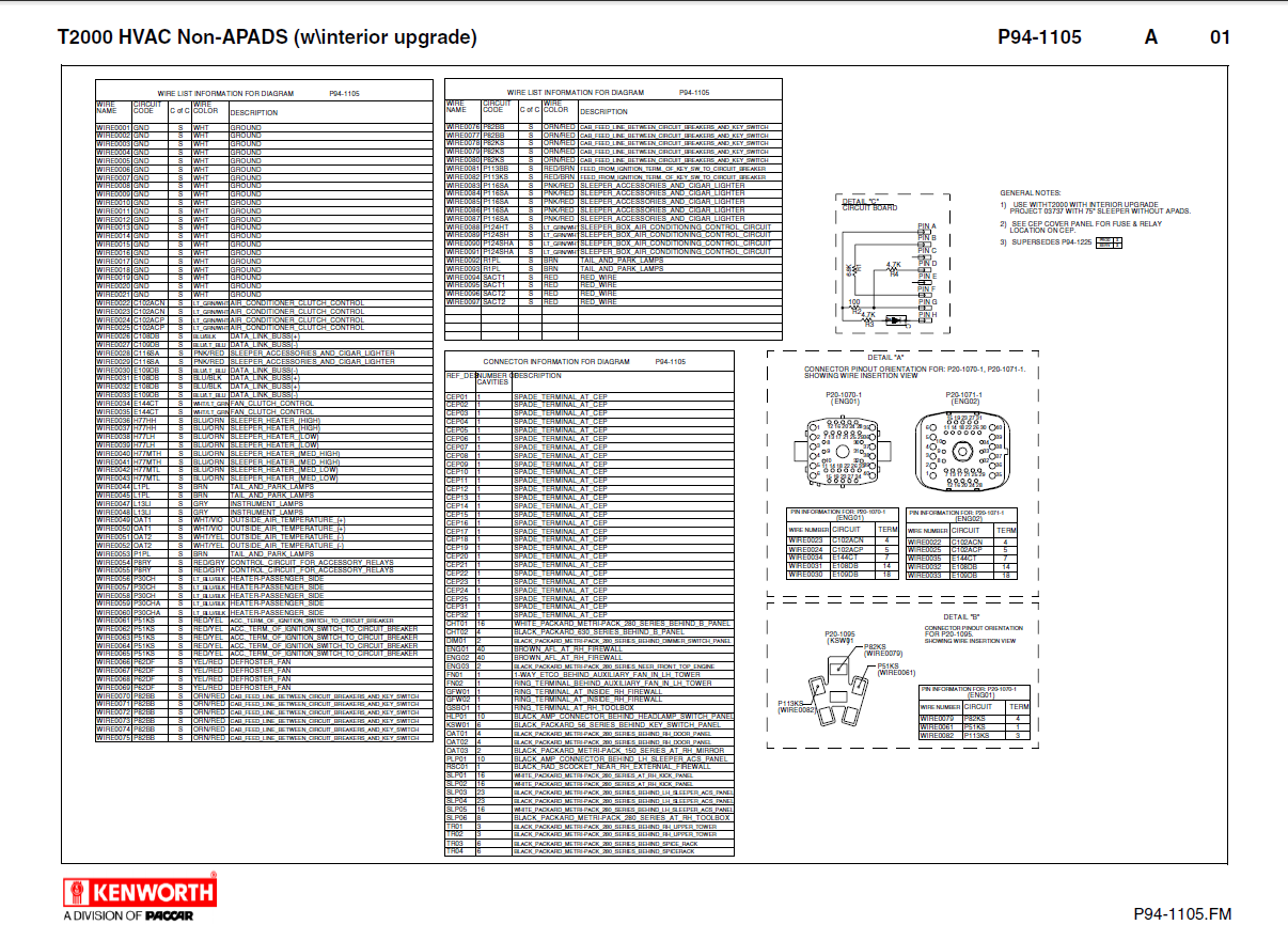
6. Jun 28, · Here is a diagram for a CH/CL from without APADS diagnostic module.
This is most likely the way your truck is wired. If you follow the wiring from the A/C compressor back you will see that it goes through the HVAC panel. 7 3/8 inch ring terminal 1 13 Pressure switch wire harness extensions 2 14 Weatherpack connectors 2 Item Description Quantity Item Description Quantity 1 Fan pressure switch (NO) 1 3 Male spade connector 2 2 Fan pressure switch (NC) 1 4 Female spade connector 2 Standard APAds Kit 7 8 1 23 Step 2 APAds® Kit Contents 4 11 12 6 3 9 4.
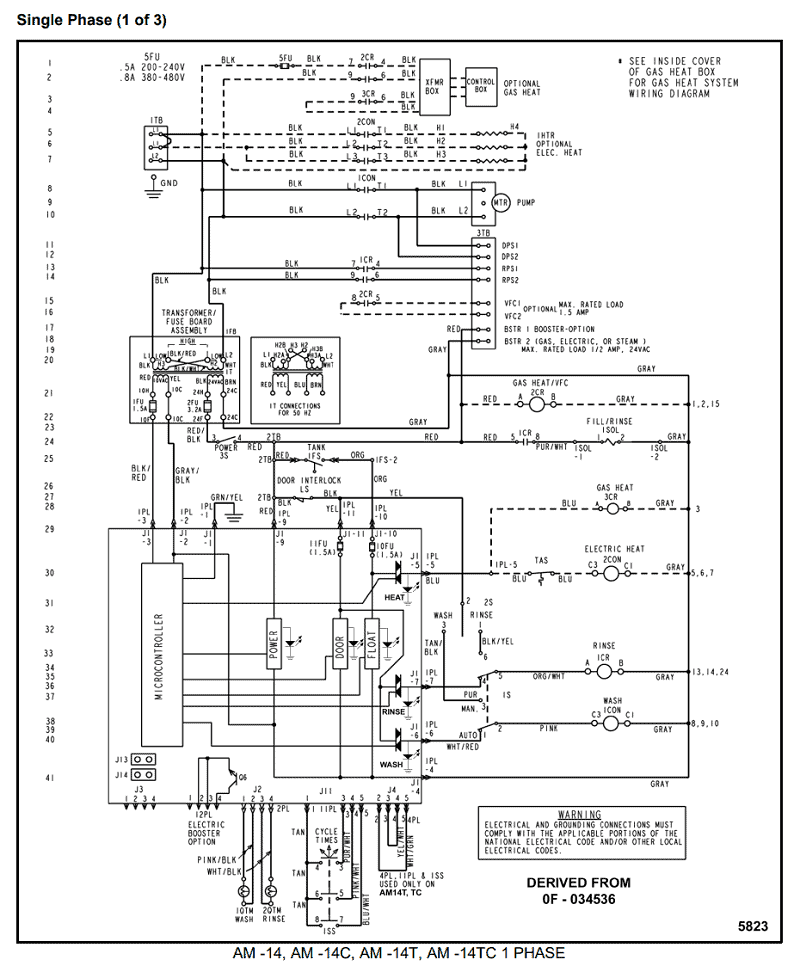
May 19, · Broken power or ground wire to control module. Repair wiring. Damaged control module.
Replace the APADS™ electronic control module, or retrofit the APADS with a binary switch. For instructions, see Service Bulletin 83– Heater and Air Conditioner, Ra Systems Troubleshooting Heavy-Duty Trucks Service Manual, Supplement RC: Mix 3rd Party Remotes w/ Crestron ControllerTrouble With A/c On 99 Ch – Modern Mack Truck General Discussion – schematron.org