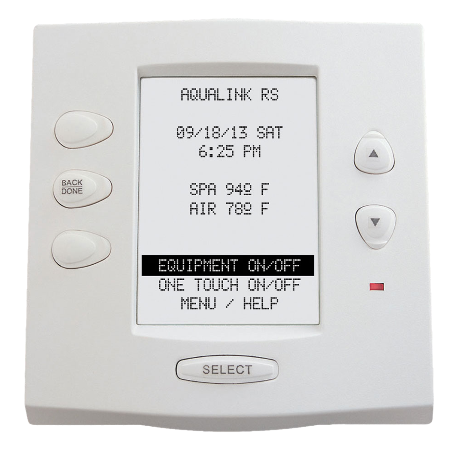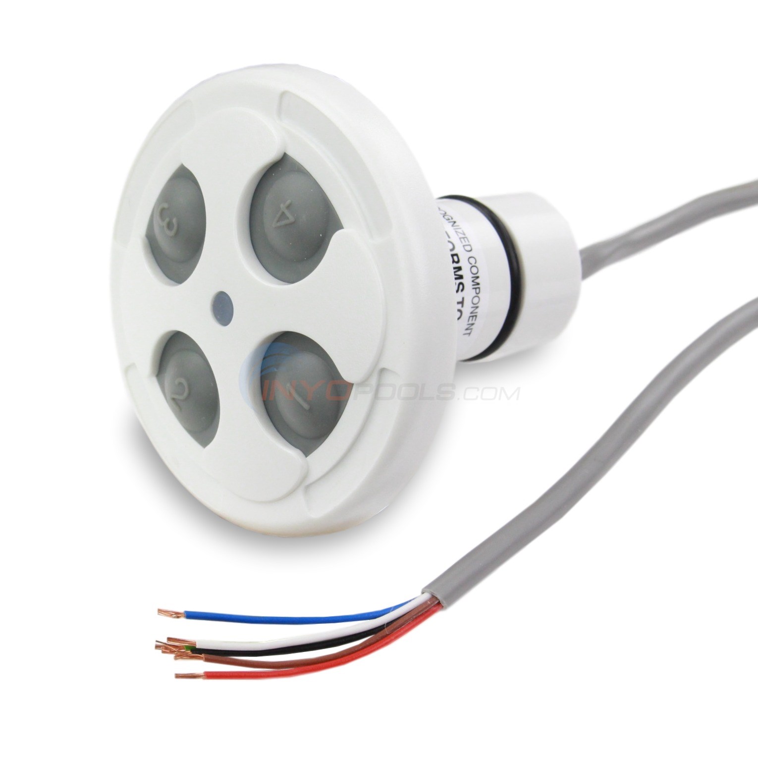
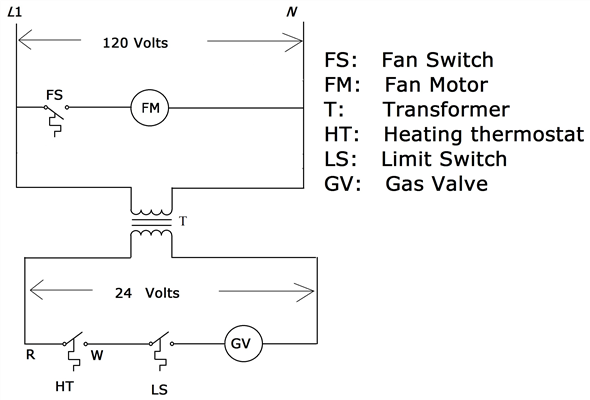
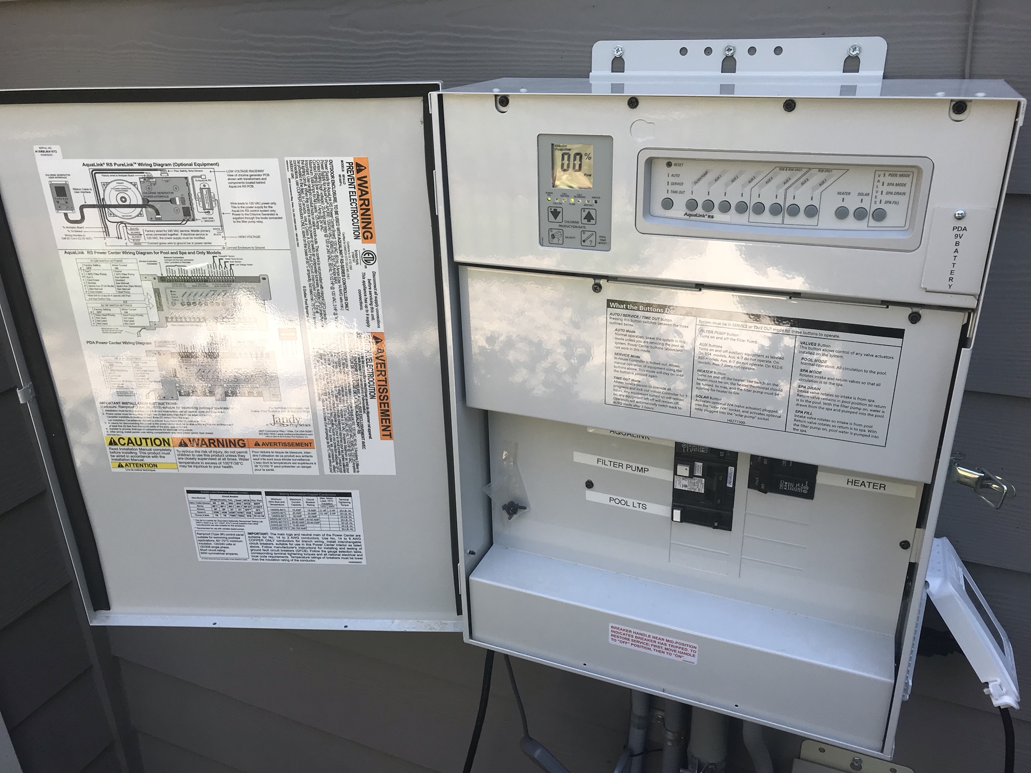
Wiring Diagrams.
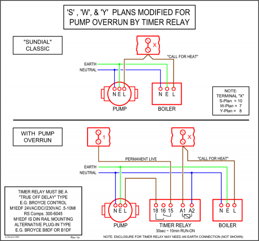
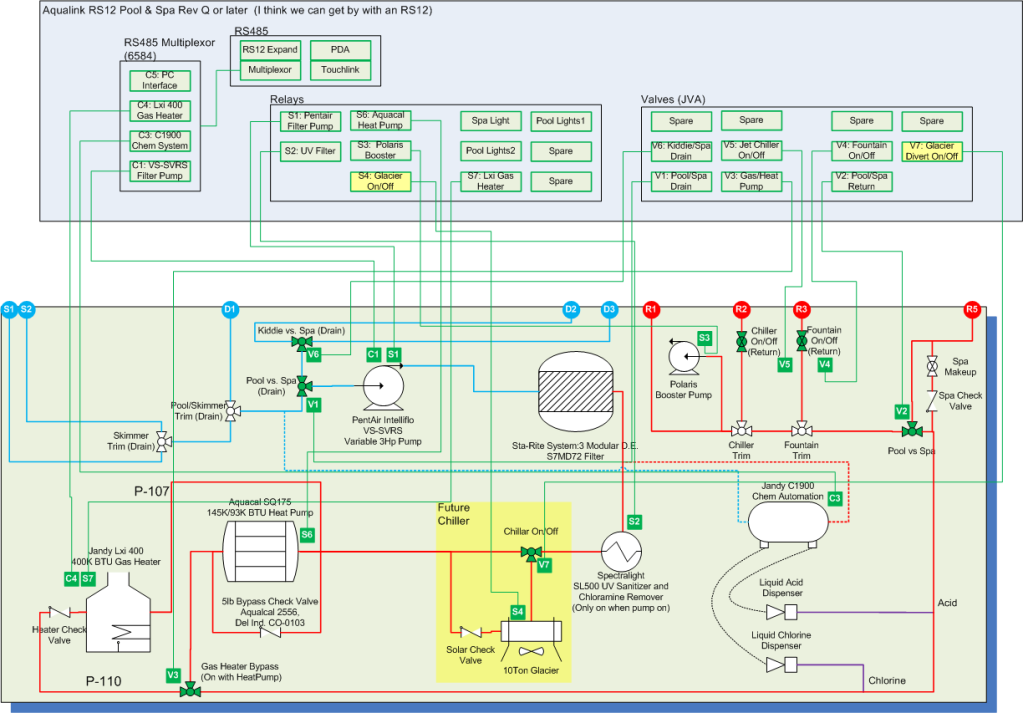
AquaLink RS Pool/Spa Combination and Pool/ .. **If an AquaLink PC is online, there must NOT be an All Button or OneTouch.
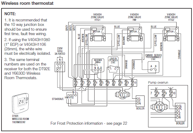
From your diagram can I presume that the pool and spa light are of the Are there any other neutrals wires wire-nut spliced in the Aqualink?. Indoor Installation of the. Cover Wall Plate.
LX10 Plastic. Compool Power Center. Low Voltage.
Raceway. Wiring Diagram.
PDA Transceiver J-box. Ground Level.
Figure 5. Volt Jandy Pool and Spa Light Wiring Diagram. Figure 6.
Volt Jandy Pool and Spa Light Wiring Diagram. GFCI. Ground.
Ground. Neutral. Black .
Installation Manual. AquaLink® RS . Package contents will depend on which AquaLink ..
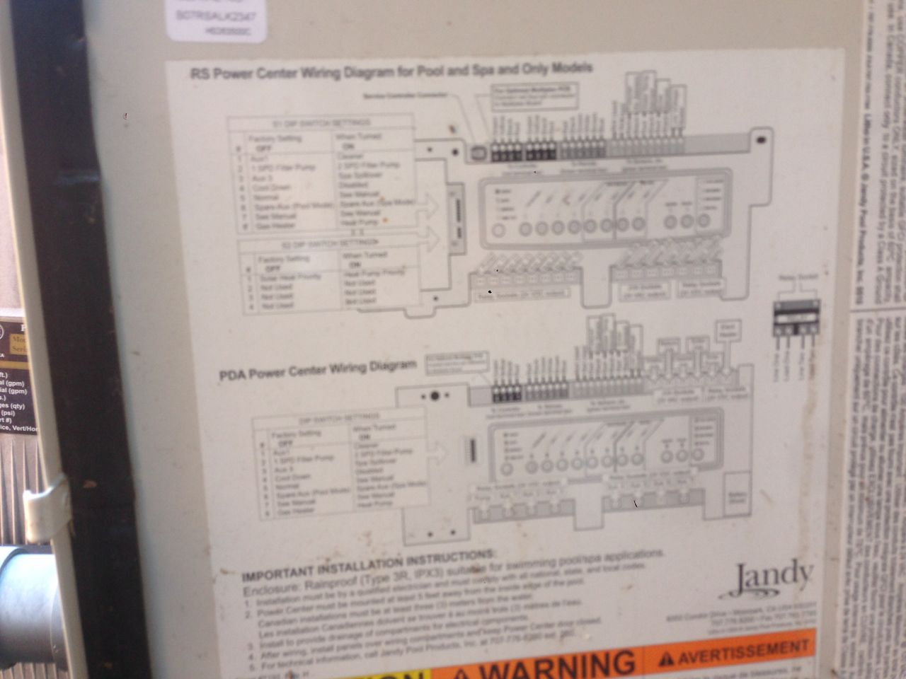
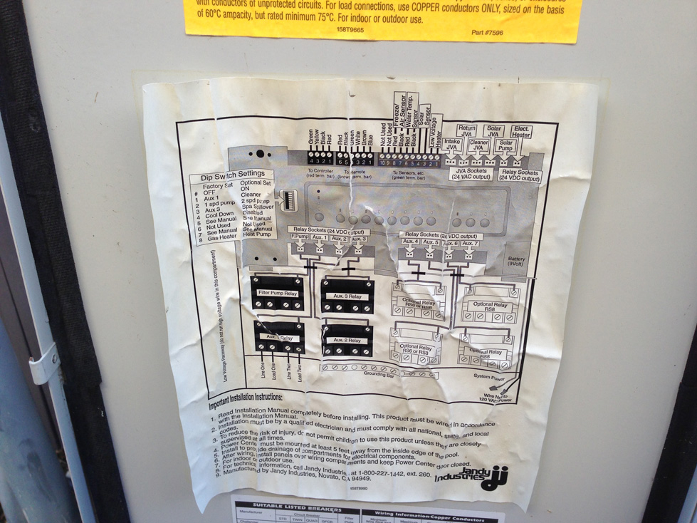
AquaLink® RS 2/6, 2/10, 2/14, 2/22, 2/30 Wiring Diagram. S1. S2.AquaLink ® RS Installation Data Power Center Surge Suppression PCB Wiring Diagram CAUTION Never connect more than two wires on each of the pins of the red terminal bar.
Use the Jandy Multiplex PCB, p/n , when more than two of the 4-wire cables are used with the system. Mounting Bracket.
Page 4 Section 1. Important Safety Instructions READ AND FOLLOW ALL INSTRUCTIONS Lire la notice technique.
All electrical work must be performed by a licensed electrician and conform to all national, state, and local codes. AquaLink® RS PDA – Pool Digital Assistant WARNING FOR YOUR SAFETY – This product must be installed and serviced by a pro fes sion al pool/spa service technician. The procedures in this manual must be followed ex act ly.
Failure to follow warning notices and instructions may result in property damage, serious injury, or death. Installation Manual All Button and OneTouchTM Control Systems WARNING FOR YOUR SAFETY – This product must be installed and serviced by a professional pool/ spa service technician. The procedures in this manual must be followed exactly. Failure to follow warning notices and instructions may result in property damage, serious injury, or death.
NOTE When connecting to the AquaLink RS, plug the JVAs into the Intake, Return and Cleaner JVA sockets. Slide DIP Switch S to the ON position.
See wiring diagram in Section 4, Figure 5. Shared Heater Check Valves (4) Spa Intake Spa Filter Spa Return Spa Pump Pool Intake Pool Pump Pool Filter Pool Return JVA JVA JVA To Solar (if installed.Owners Manuals | Zodiac Pool Systems, Inc.JANDY AQUALINK RS INSTALLATION MANUAL Pdf Download.
