Not only do you get a solid and reliable connection, but the adapters are secured to the HDMI cable so they can’t get lost before the next presentation!.
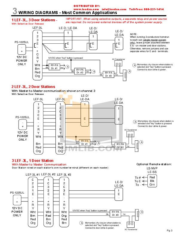
Bosch. Type. Relay Wiring.
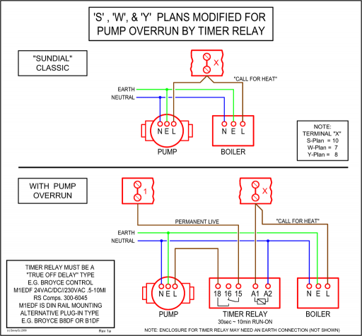
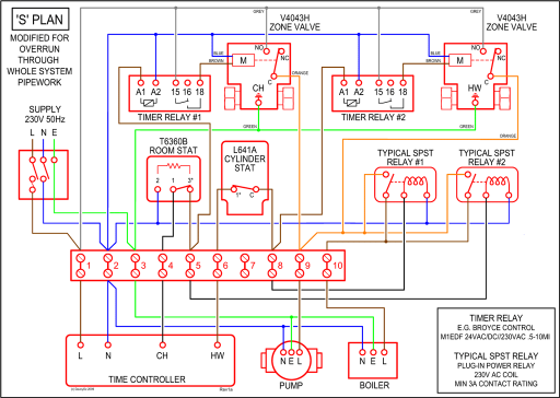
Relay In A Box Explained
Diagrams. Page 2.
2. Page 3. 3.
Page 4. 4. Page 5. 5.
Page 6. 6.
Page 7. 7. Page 8.
8. Page 9.
9. Page Page Page Read our guide to relays found in vehicle electrical systems.
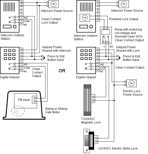
Wiring Diagrams
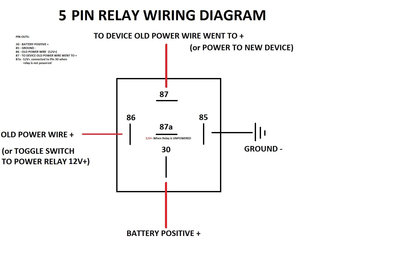
to activate one or more relays that then complete one or more other circuits and so carry out. The main purpose of a relay is to switch electrical circuits off and on at given times and allow circuits to be automated. A great advantage with relays is the ability. Relay wiring diagrams of dozens of 12V 5 pin SPDT automotive relay wiring configurations for mobile electronics applications.rma (refer to conversion wiring diagram form instead of converting the rc to rm).
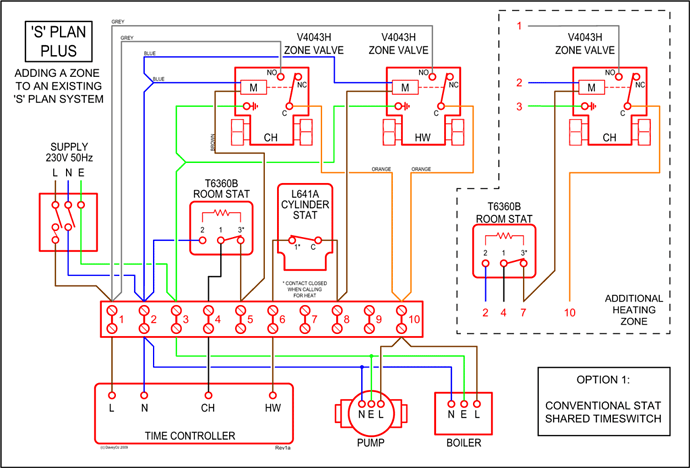
if the application has external purge timing and/or an external interrupted pilot relay, then convert to rm see conversion wiring diagram, form series conversion wiring diagram. A relay consists of an electromagnet that receives an electric signal and converts it to a mechanical action and a switch that open and closes the electric circuit. Schematic Diagram Showing the Principle of .
Jun 25, · Here’s how it works: The GE RR7 relay is a ‘latching relay’. This simply means that when you touch a light switch to turn on a light, it sends a pulse of low voltage (24 volts DC) to the relay on the RED wire and latches it ON for the light to be switched on by the relay.
It requires a pulse of voltage on the BLACK wire to turn it OFF.5/5. Convenient connections for thermostat and heating and cooling equipment wiring.
Mounts on standard 4 x 4 junction box. Can be mounted in any indoor location without additional enclosure.
Relay is easily replaced without disturbing wiring. Includes relay enclosure. 3.
All wiring must comply with applicable local electrical codes, ordinances, and regulations. 4. All line voltage terminal wiring shall be no.
14, 16 or 18 copper conductor TTW (60C) or THW (75C) or THHN (90C), volt insulation wire. A maximum of two conductors can be .DL-AR – DIGITALINX SECURE ADAPTER RINGPrinciples of General Purpose Relays | OMRON Industrial Automation