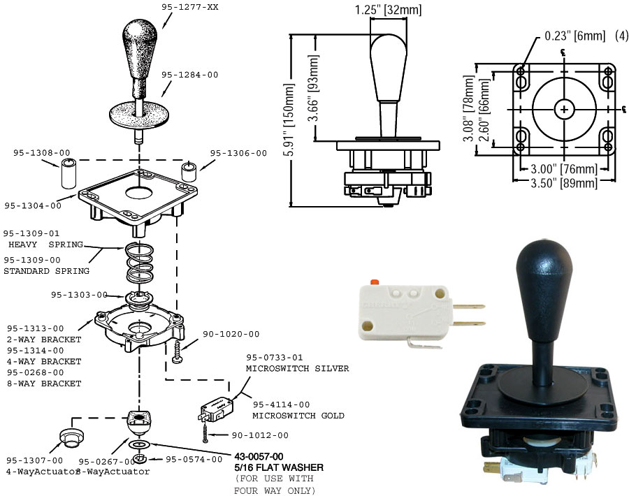
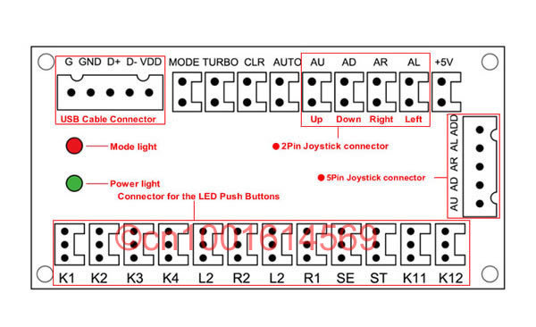
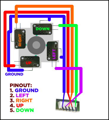
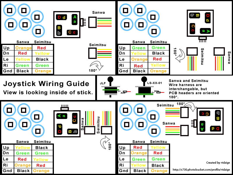
Wiring a Happ Joystick to a zero delay encoder. Here is a wiring diagram for those LED ZD encoders that might help: «Last Edit: September. What is an encoder?
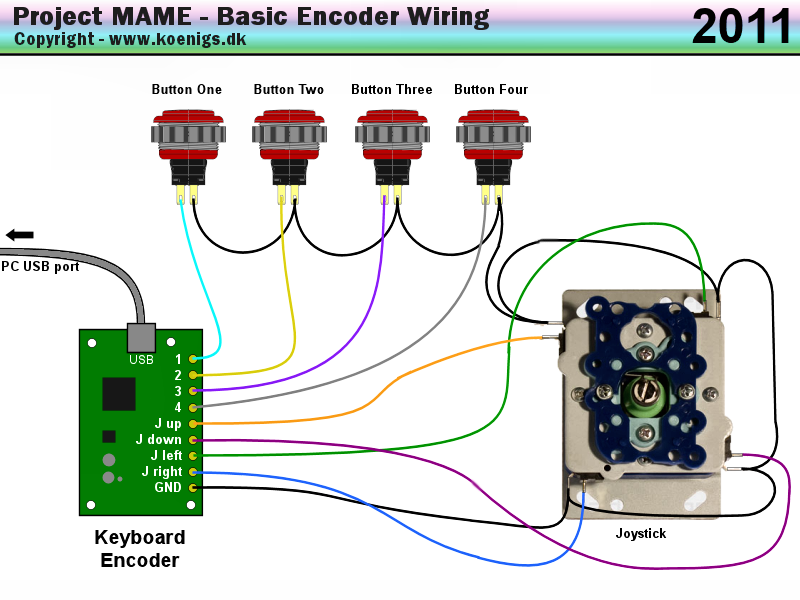
An encoder is a device translating the input from your arcade controls to a language your PC or console would understand. Most translate.
Right. 1 10 Button 1 □.
None. 18 9. GND.
Left. 2 11 Button 2.
X. VCC.
17 8. Button 8 R2.
Raspberry Pi – Building an Arcade Fightstick / Joystick
Down. 3 12 Button 3 O.
GND. 16 7. Button 7 L2.
Up. 4 13 Button 4 △ .
Up. What is an encoder?
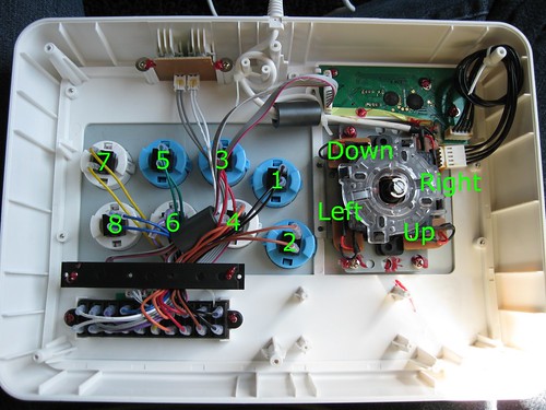
An encoder is a device translating the input from your arcade controls to a language your PC or console would understand. Most translate. We are going to wire up the Joystick first, so grab that and the ribbon cable.
Plug one Arcade Joystick, Buttons & Encoder Bundle for Raspberry Pi. £ Anyone have a schematic so i can build a pulse generator for this purpose?
Reply.Circuit Diagram. Use the diagram above to reference the wired connections. The length of wires are not exact, this is just a visual representation of the circuit.
The Adafruit Arcade Bonnet has six JST connectors for quick-connect wires. To add more buttons and a mini analog joystick, we’ll need to solder the wire connections.
Circuit Diagram. Use the diagram above to reference the wired connections. The length of wires are not exact, this is just a visual representation of the circuit.
The Adafruit Arcade Bonnet has six JST connectors for quick-connect wires. To add more buttons and a mini analog joystick, we’ll need to solder the wire connections. Arcade Machine Jamma wiring Harness / Loom 3′ extension lead Cable tidy kit.
£ Arcade machine cable tidy kit. X-Arcade Wiring Harness.
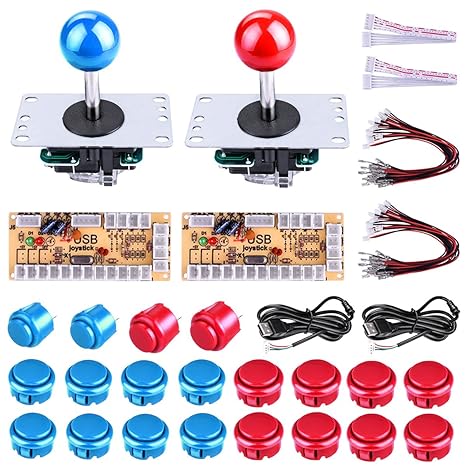
Wiring harness for X-Arcade PCB to wire X-Arcade joysticks and buttons to the PCB. Recommended for replacement of your existing wiring harness or if your project using an X-Arcade PCB requires wider/longer wires/cables.
Circuit Diagram. Use the diagram above to reference the wired connections. The length of wires are not exact, this is just a visual representation of the circuit. The Adafruit Arcade Bonnet has six JST connectors for quick-connect wires.
To add more buttons and a mini analog joystick, we’ll need to solder the wire connections.Build Your Own Arcade Controls – WiringBuild A Home Arcade Machine » Wiring the Controls