
The Arduino Mega 2560 is a popular microcontroller board that is widely used in electronic projects and prototyping. It is based on the ATmega2560 microcontroller and offers a larger number of digital and analog pins compared to the Arduino Uno.
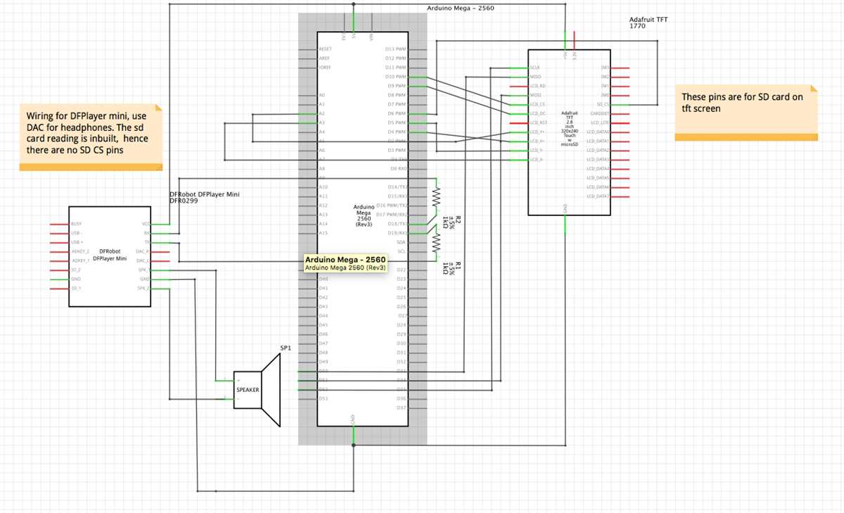
When working on Arduino projects, it is important to have a clear understanding of the wiring diagram in order to connect various components and devices correctly. The wiring diagram provides a visual representation of how the different components of the circuit are connected to the Arduino board.
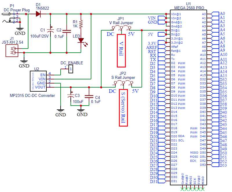
The Arduino Mega 2560 wiring diagram typically includes the pins for power, ground, digital input/output, and analog input/output. It also shows the connections for other components such as sensors, motors, displays, and communication modules.
Having a well-designed wiring diagram can simplify the process of building and debugging Arduino projects, as it allows you to easily identify any mistakes or errors in the connections. It also serves as a reference for future projects or modifications. In this article, we will explore a typical wiring diagram for the Arduino Mega 2560 and discuss its components and connections in detail.
What is Arduino Mega 2560?
The Arduino Mega 2560 is a microcontroller board based on the ATmega2560. It is one of the most powerful Arduino boards, offering a larger number of digital and analog inputs/outputs compared to other Arduino models. This makes it ideal for projects that require a large number of sensors or actuators.
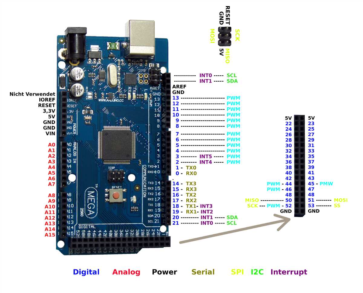
The Arduino Mega 2560 has 54 digital input/output pins, 16 analog inputs, 4 UARTs (hardware serial ports), a 16 MHz quartz crystal, a USB connection for programming and power, an ICSP header, and a reset button. It also has a larger memory compared to other Arduino boards, with 256KB of flash memory and 8KB of SRAM.
With its numerous pins and peripherals, the Arduino Mega 2560 can be used to create a wide range of projects, from home automation systems and robotics to data logging and interactive art installations. Its versatility and expandability make it a popular choice among hobbyists, makers, and professionals alike.
Overview of Arduino Mega 2560
The Arduino Mega 2560 is a microcontroller board based on the ATmega2560. It is one of the most powerful Arduino boards available, providing users with a wide range of functionalities and features. The board has 54 digital input/output pins, 16 analog inputs, 4 UARTs (hardware serial ports), a 16 MHz quartz crystal, a USB connection, power jack, and a reset button. It also has a large number of external interrupts and plenty of memory for storing programs and data.
The Arduino Mega 2560 is often used in projects that require a high number of input/output pins or complex tasks. It is particularly suitable for robotics and automation systems, due to its extensive capabilities and compatibility with various sensors, actuators, and other peripherals.
Main Features of Arduino Mega 2560:
- Microcontroller: ATmega2560
- Operating Voltage: 5V
- Digital I/O Pins: 54 (of which 15 can be used for PWM output)
- Analog Input Pins: 16
- UARTs: 4
- Flash Memory: 256 KB (8 KB used by bootloader)
- SRAM: 8 KB
- EEPROM: 4 KB
- Clock Speed: 16 MHz
- Power Source: USB or External power supply
In addition to its technical specifications, the Arduino Mega 2560 also benefits from a large and active community of users. This means that there is a wealth of resources, libraries, and example code available for users to learn from and build upon. The board is fully compatible with the Arduino IDE, making it easy to program and upload code to the board.
With its extensive features and capabilities, the Arduino Mega 2560 is a popular choice for advanced projects and applications. Whether you are a hobbyist or a professional, this board provides the flexibility and power needed to bring your ideas to life.
The Importance of a Wiring Diagram
In the world of electronics and circuitry, a wiring diagram is an essential tool that provides a visual representation of the connections and components in a particular circuit or system. It is a detailed schematic diagram that helps in understanding the wiring and electrical connections of a circuit board or device.
Understanding the connections: A wiring diagram shows the electrical connections between different components, such as resistors, capacitors, transistors, and sensors. It helps in understanding how the various components are connected and how the system functions as a whole.
Troubleshooting and debugging: When there is an issue or malfunction in a circuit or system, a wiring diagram can be invaluable in troubleshooting the problem. By following the diagram, one can identify any loose connections, faulty components, or incorrect wiring that may be causing the issue.
Maintaining consistency: A wiring diagram ensures that the connections and wiring are consistent and accurate. It serves as a reference guide for technicians and engineers, making it easier to replicate the circuit or system in different environments or during repairs or modifications.
Documentation and communication: Wiring diagrams are also important for documentation and communication purposes. They allow engineers, technicians, and other stakeholders to communicate effectively by providing a standardized visual representation of the wiring and connections.
Improving safety: A well-documented wiring diagram can help in improving safety by ensuring that the electrical connections are made correctly and that there are no potential hazards or risks present. It allows for proper grounding, isolation, and protection measures to be implemented.
Overall, a wiring diagram is a crucial tool in the field of electronics and circuitry. It helps in understanding, troubleshooting, maintaining consistency, documenting, and improving safety in various electrical systems and circuits.
The Purpose and Benefits of Understanding the Arduino Mega 2560 Wiring Diagram
The Arduino Mega 2560 is a popular microcontroller board that offers extensive capabilities for electronics projects. Understanding the wiring diagram specific to this board can greatly enhance your ability to successfully utilize its features and expand upon its functionalities. By gaining a deeper understanding of the board’s wiring, you can harness its full potential and efficiently create complex projects tailored to your needs.
One of the key benefits of familiarizing yourself with the Arduino Mega 2560 wiring diagram is improved troubleshooting and debugging. As you work on projects, it is not uncommon to encounter problems or unexpected behavior. By referencing the wiring diagram, you can quickly identify any potential wiring issues and efficiently troubleshoot the problem, saving valuable time and effort.
Benefits of Understanding the Arduino Mega 2560 Wiring Diagram:
- Efficient Project Development: With a comprehensive understanding of the wiring, you can design and implement projects more efficiently, minimizing errors and maximizing functionality. This allows you to create advanced projects that take full advantage of the features provided by the Arduino Mega 2560.
- Customization and Expansion: Understanding the wiring diagram allows you to customize and expand the capabilities of the Arduino Mega 2560. By knowing how the different components are connected, you can easily incorporate additional modules or sensors, opening up endless possibilities for project development.
- Troubleshooting and Debugging: The wiring diagram serves as a helpful reference when troubleshooting and debugging your projects. By using the diagram to verify correct wiring connections, you can quickly identify and resolve any issues, ensuring smooth operation of your project.
- Learning and Education: Studying the wiring diagram is an excellent way to deepen your understanding of electronics and microcontroller systems. As you analyze the connections and components, you can learn about the underlying principles and gain valuable knowledge for future projects.
- Collaboration and Documentation: The wiring diagram is a crucial tool for collaboration and documentation purposes. By sharing the diagram with others, you can easily communicate the project’s wiring configuration and collaborate with fellow electronics enthusiasts or colleagues.
Components Required for Wiring Arduino Mega 2560
When it comes to wiring an Arduino Mega 2560, there are several components that are essential for the process. These components ensure that everything is connected properly and that the Arduino board can function as intended. Here is a list of the components you will need:
- Arduino Mega 2560: This is the main microcontroller board that you will be wiring. It is the heart of the project and is responsible for executing the code and controlling the connected components.
- Breadboard: A breadboard is used to create temporary connections between components. It allows you to quickly and easily test circuits without the need for soldering.
- Jumper wires: Jumper wires are used to make the connections between the Arduino Mega 2560 and other components. They typically have female ends that can be plugged into the board and male ends that can be inserted into the breadboard or other components.
- Resistors: Resistors are used to limit the current flowing through certain components or to create voltage dividers. Depending on your project, you may need resistors of different values.
- LEDs: LEDs are used to visually indicate the status or output of the Arduino. They can be connected to digital pins and controlled through the code to turn on or off.
- Push buttons: Push buttons are used as input devices. They can be connected to digital pins and used to trigger certain actions or events in the code when pressed.
- Sensors: Depending on your project, you may need various sensors such as temperature sensors, light sensors, or motion sensors. These sensors can be connected to the Arduino Mega 2560 and provide data for your code to process.
By having these essential components, you will be able to wire your Arduino Mega 2560 and start experimenting with various projects and circuits. Make sure to refer to the wiring diagram specific to your project to ensure proper connection of these components.
List of Essential Hardware Components
When it comes to working with Arduino Mega 2560, there are several essential hardware components that you will need. These components are crucial for building and connecting your projects, and they allow you to interact with the Arduino board and control different electronic devices.
1. Arduino Mega 2560 Board: The heart of your project, the Arduino Mega 2560 board is a microcontroller board based on the ATmega2560. It provides a large number of digital and analog I/O pins, making it suitable for complex projects.
2. Breadboard: A breadboard is a crucial tool for prototyping and testing circuits. It allows you to connect different components together without the need for soldering. With its grid of interconnected holes, you can easily create temporary circuits and modify them as needed.
3. Jumper Wires: Jumper wires are used to make connections between various components on a breadboard or directly to the Arduino board. They provide a quick and easy way to establish electrical connections without soldering.
4. LEDs: Light-emitting diodes (LEDs) are used to indicate the status of your project or as a visual feedback. You can easily connect LEDs to the Arduino Mega 2560 board to create simple lighting effects or use them as indicators.
5. Resistors: Resistors are essential components that help regulate the flow of current in a circuit. They are commonly used to prevent LEDs from burning out by limiting the amount of current flowing through them.
6. Capacitors: Capacitors store and release electrical charge, helping stabilize voltage levels in a circuit. They are often used to reduce noise, filter out unwanted frequencies, or provide backup power during voltage drops.
7. Push Buttons: Push buttons are used to create user input in your projects. They allow users to interact with your Arduino Mega 2560 board and trigger different actions or control different devices.
8. Sensors: Sensors are used to measure and detect various physical quantities, such as temperature, humidity, light, motion, or distance. They provide input to your Arduino board, allowing it to respond to the surrounding environment.
9. Motors: Motors are used for controlling movement in projects such as robotics or automation. They can be connected to the Arduino board with the help of motor drivers and enable precise control over speed and direction.
10. Display Modules: Display modules, such as LCD screens or OLED displays, allow you to show information or interaction options to the user. They can be connected to the Arduino board and used to display sensor readings, messages, or menus.
These are just some of the essential hardware components you will need when working with the Arduino Mega 2560 board. Depending on your project requirements, you may need additional components, such as relays, transistors, or wireless communication modules. Understanding and using these components will help you unleash the full potential of your Arduino Mega 2560 board and bring your projects to life.
Step-by-Step Guide on Wiring Arduino Mega 2560
If you are working with Arduino projects that require more pins and memory, the Arduino Mega 2560 is the ideal board for you. With its 54 digital input/output pins and 256 KB of flash memory, the Mega 2560 offers enhanced capabilities compared to other Arduino boards. In this step-by-step guide, we will explain how to wire the Arduino Mega 2560 to get started with your projects.
Requirements:
- Arduino Mega 2560 board
- USB cable
- Breadboard
- Jumper wires
- LEDs
- Resistors
Step 1: Connect the Arduino Mega 2560 to your computer
To begin, connect one end of the USB cable to your Arduino Mega 2560’s USB port, and the other end to an available USB port on your computer. This will provide power to the board and enable communication between the Arduino and your computer.
Step 2: Connect the power and ground pins
Next, connect the 5V pin on the Arduino Mega 2560 to the positive rail of the breadboard using a jumper wire. Then, connect the GND (ground) pin on the Arduino Mega 2560 to the negative rail of the breadboard. These connections will provide power and a common ground for your circuits.
Step 3: Connect an LED to the Arduino Mega 2560
To test the board, let’s connect an LED to one of the digital pins of the Arduino Mega 2560. Insert the positive leg of the LED (the longer leg) into one of the breadboard rows connected to the positive rail. Connect a resistor to the other leg of the LED, and then connect the other end of the resistor to the digital pin on the Arduino Mega 2560. Finally, connect the negative leg of the LED to the negative rail on the breadboard.
Step 4: Upload a test sketch
Once the LED is connected, open the Arduino IDE on your computer and select the appropriate board (Arduino Mega 2560) and port. Then, write a simple test sketch that will turn the LED on and off. Upload the sketch to the Arduino Mega 2560 and observe the LED’s behavior. If the LED blinks, it means the wiring is correct.
Step 5: Expand your projects
Now that you have successfully wired and tested the Arduino Mega 2560, you can start exploring its capabilities. With its numerous pins and extended memory, you can connect various sensors, modules, and actuators to create more complex projects. Just remember to consult the datasheets and tutorials for each component to ensure proper wiring and usage.
With this step-by-step guide, you should now have a basic understanding of how to wire the Arduino Mega 2560 and start experimenting with it. Remember to always double-check your connections and exercise caution when working with electronics. Happy tinkering!
Instructions for Properly Connecting the Components
Before starting the wiring process, make sure you have all the necessary components and tools ready. This includes an Arduino Mega 2560 board, a breadboard, jumper wires, and the specific components you want to connect, such as LEDs, sensors, or motors.
Follow these steps to properly connect the components:
- Step 1: Connect the Arduino Mega 2560 board to the breadboard using jumper wires. Ensure that the power pins (5V and GND) on the Arduino are correctly connected to the breadboard’s power rails.
- Step 2: Identify the pins on the Arduino Mega 2560 board that correspond to the specific components you want to connect. Refer to the datasheets or pinout diagrams for the components to determine the necessary connections.
- Step 3: Connect the components to the Arduino Mega 2560 board using jumper wires. Make sure to connect the correct pins on the components to the corresponding pins on the Arduino.
- Step 4: If necessary, connect additional components, such as resistors or capacitors, to the circuit. Follow the component’s datasheet or schematic to ensure proper connections.
- Step 5: Check the wiring connections for any loose or incorrect connections. Ensure that all the wires are securely plugged into the Arduino and the breadboard.
- Step 6: Test the circuit by uploading a basic Arduino sketch that controls the connected components. Make sure the code is properly written to interact with the components connected to the Arduino Mega 2560 board.
Properly connecting the components is crucial to ensure the circuit functions correctly and safely. Double-check your connections before powering on the Arduino Mega 2560 board and running any code. Always refer to the datasheets or pinout diagrams for the specific components you are working with to ensure accurate wiring.