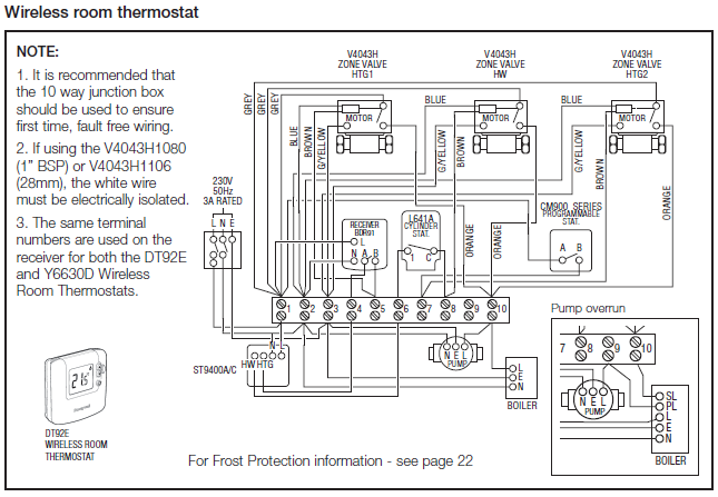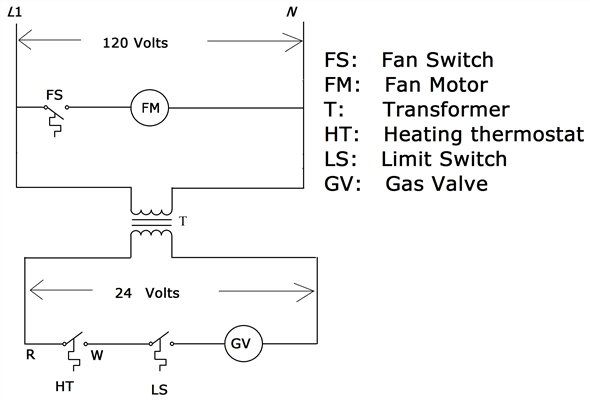
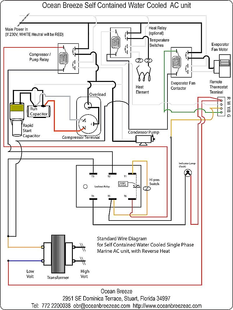
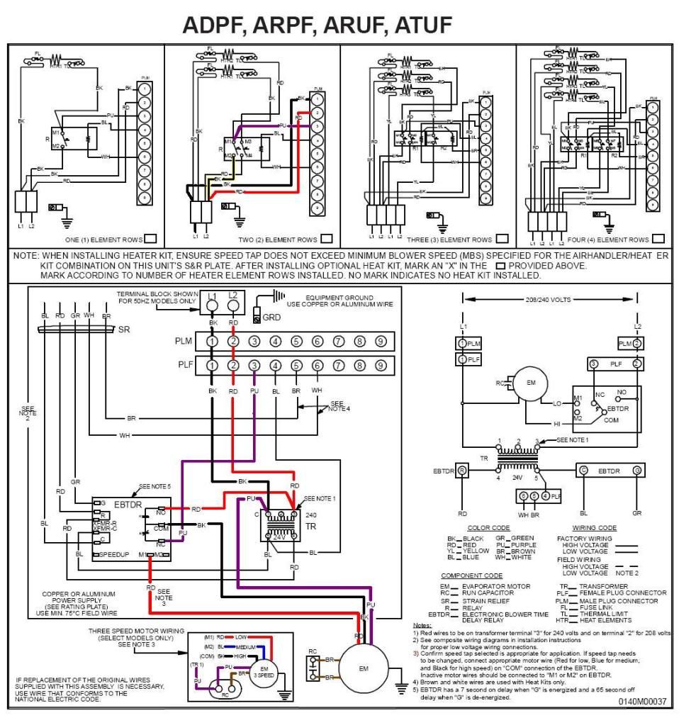
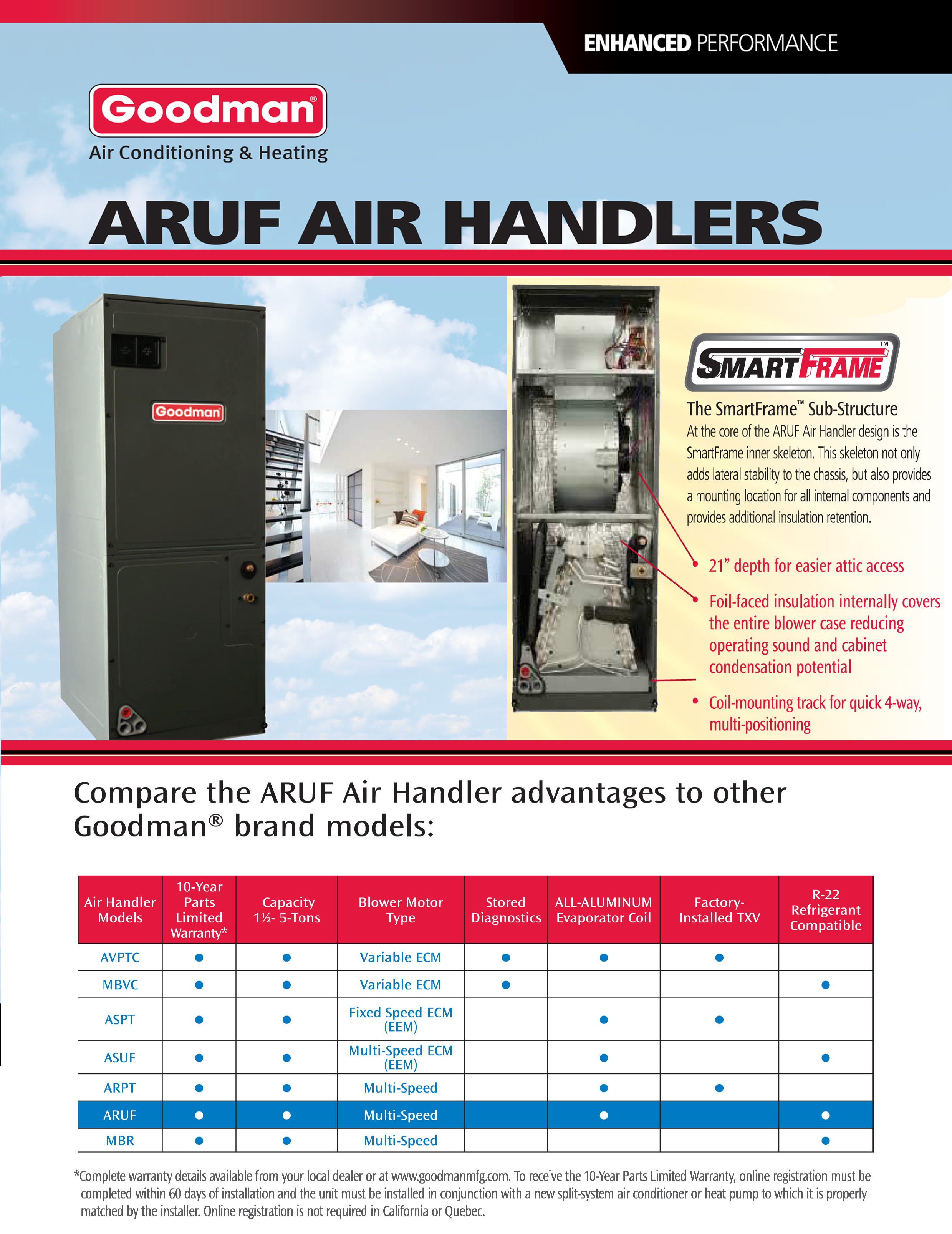
15 KW breakered heat strip for Goodman ARUF, AVPTC, ARPT, ASPT, Video · Wiring Diagrams . ARUF**14/ARPT**14/ASPT**14/ASUF**14/AUPTC**14/ AVPTC**14 Average Customer Review: 5 of 5 Total Reviews: 1 Write a review.
5. 8.
HEAT KIT NOMINAL kW. CFM.
Table 2 . mostat Wiring” section of this manual for typical low voltage.
Special Warning for Installation of Furnace or Air Handling Units in. Enclosed Areas ..
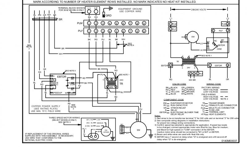
manual for the ARUF, ARPF and ARPT models for typical low voltage. Goodman ARPT**14** Manual Online: Maximum Overcurrent Protection (mop), Electrical Connections this manual for typical low voltage wiring connections.
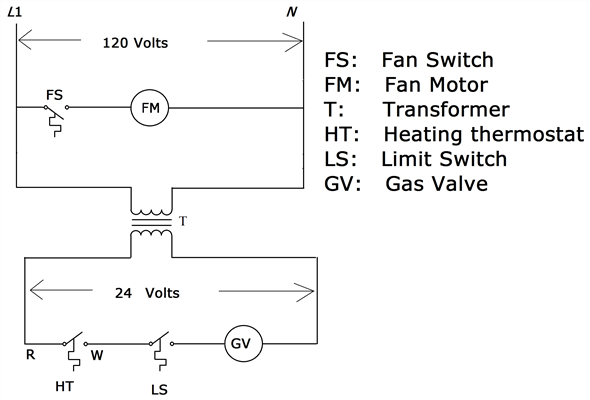
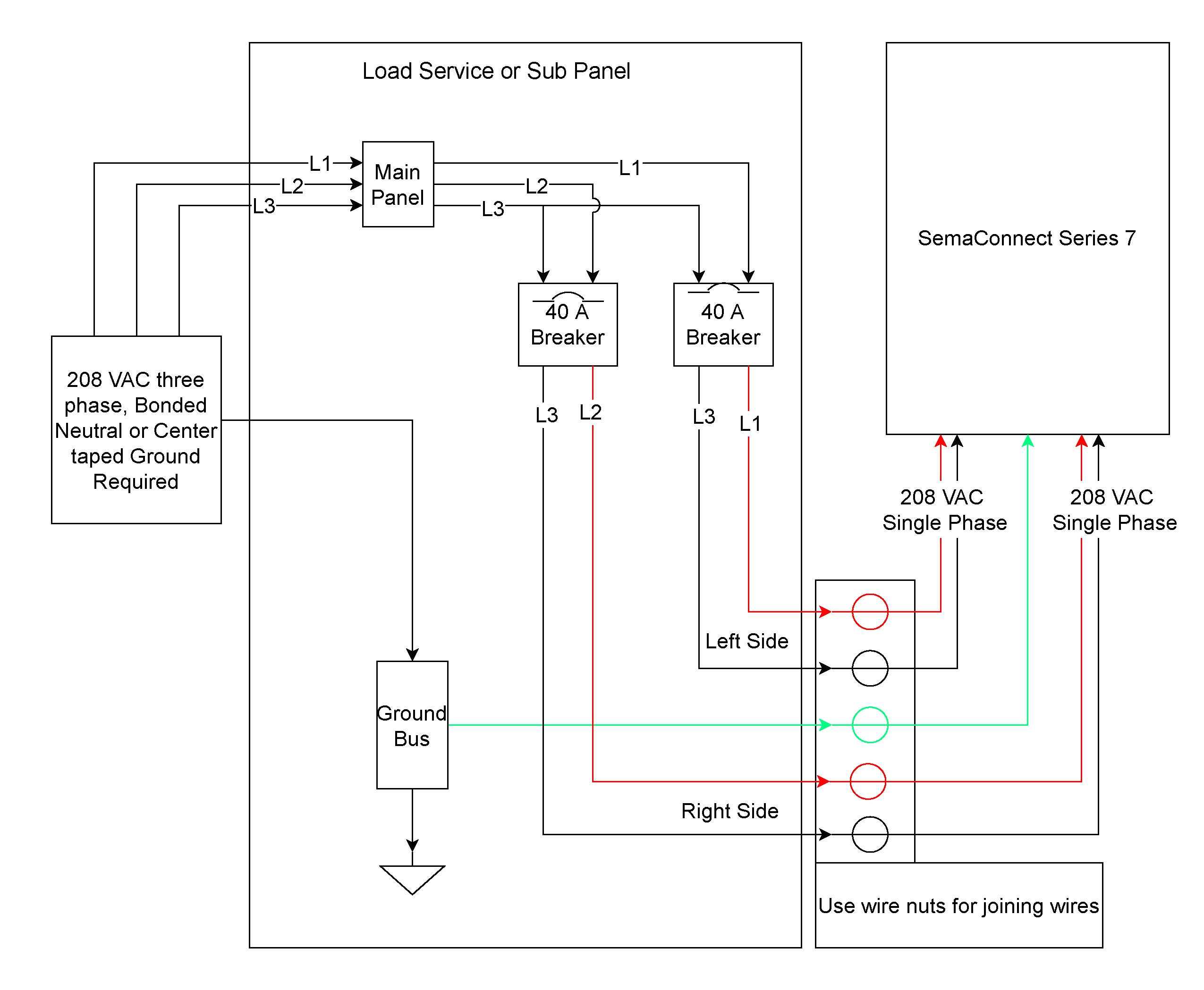
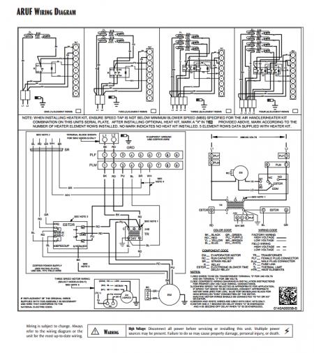
15 KW breakered heat strip for Goodman ARUF, AVPTC, ARPT, ASPT, Video · Wiring Diagrams . ARUF**14/ARPT**14/ASPT**14/ASUF**14/AUPTC**14/ AVPTC**14 Average Customer Review: 5 of 5 Total Reviews: 1 Write a review.ARUF wiRing diAgRAM Wiring is subject to change. Always refer to the wiring diagram or the unit for the most up-to-date wiring.
⚠ Warning High Voltage: Disconnect all power before servicing or installing this unit. Multiple power sources may be present. Failure to do so may cause property damage, personal injury, or death.
⚡ USE COPPER WIRE. ARUF**14** / ASPT**14** 1 Important Safety Instructions The following symbols and labels are used throughout this manual to indicate immediate or potential safety hazards.
It is the owner’s and installer’s responsibility to read and comply with all safety information and instructions accom-panying these symbols. Failure to heed safety.
ARUF**14** 3 5 6 8 10 15 19 20 25 18 24 30B 30C 36 42 48 60 Minimum CFM required for Heater Kits *ARUF ARPT HEATER (kW). ATUF/ARUF/ARPF/ADPF 10 KW & BELOW HEAT PUMP O Y R #18 GA.
5 WIRE (OPTIONAL) OUTDOOR THERMOSTAT CLOSE ON TEMPERATURE FALL Page Aspf Thermostat Connections. ASPF THERMOSTAT CONNECTIONS The following composite wiring diagrams detail various configurations in which the ASPF air handlers can be used.
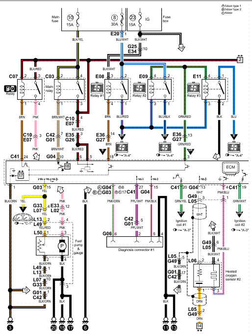
ARUF wiRing diAgRAM Wiring is subject to change. Always refer to the wiring diagram or the unit for the most up-to-date wiring. ⚠Warning High Voltage: Disconnect all power before servicing or installing this unit.
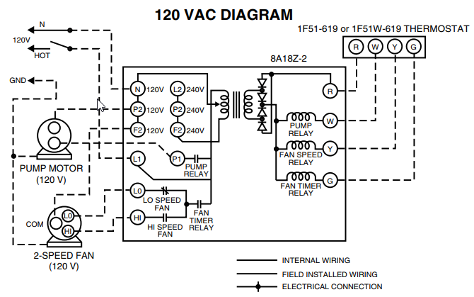
Multiple power sources may be present. Failure to .Goodman Air Handler Wiring Diagram Electric | Wiring LibraryARUF**14**/ARPT**14** ASPT**14**/ASUF**14 | schematron.org
