It is the design of the internal driver circuit components that will determine .. Providing a matrix, chart or electronic app to inform consumers and electricians of ..
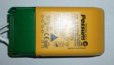
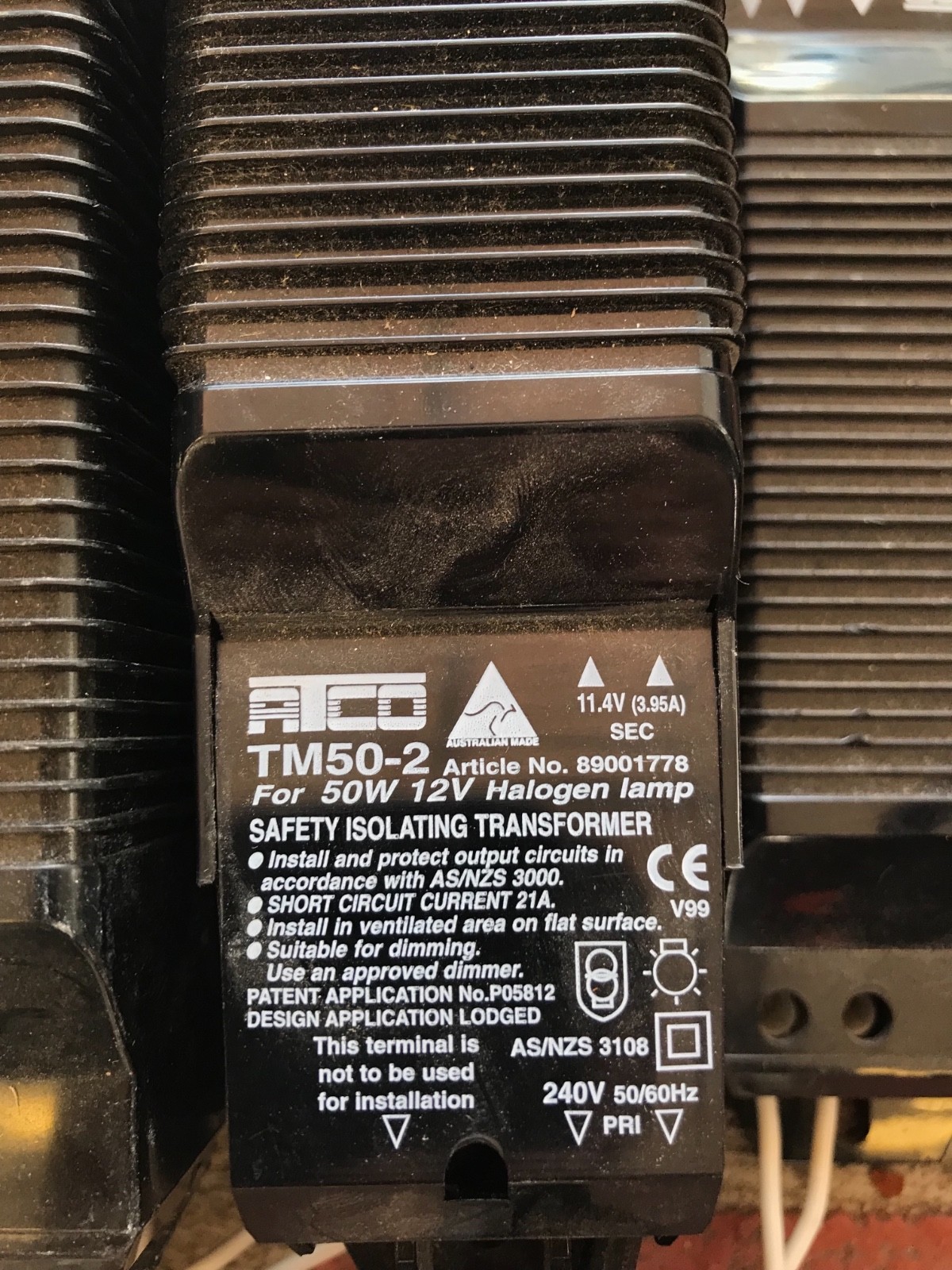
ATCO TM Iron Core, Fail / Dimming Range % – 50%. If I need to include transformer installation this will jack up the cost my existing halogens: ATCO TM’s (which I am led to believe are “iron. Australian made iron core transformers, comes with lamp holders and 2-pin plug attached!
Tested and all working, lamp holders in good condition, plugs are. Common Low Voltage (V a.c.

50Hz) and Extra Low Voltage (12V a.c. 50Hz). No polarization required (equivalent to parallel connection).
2. Constant Current .
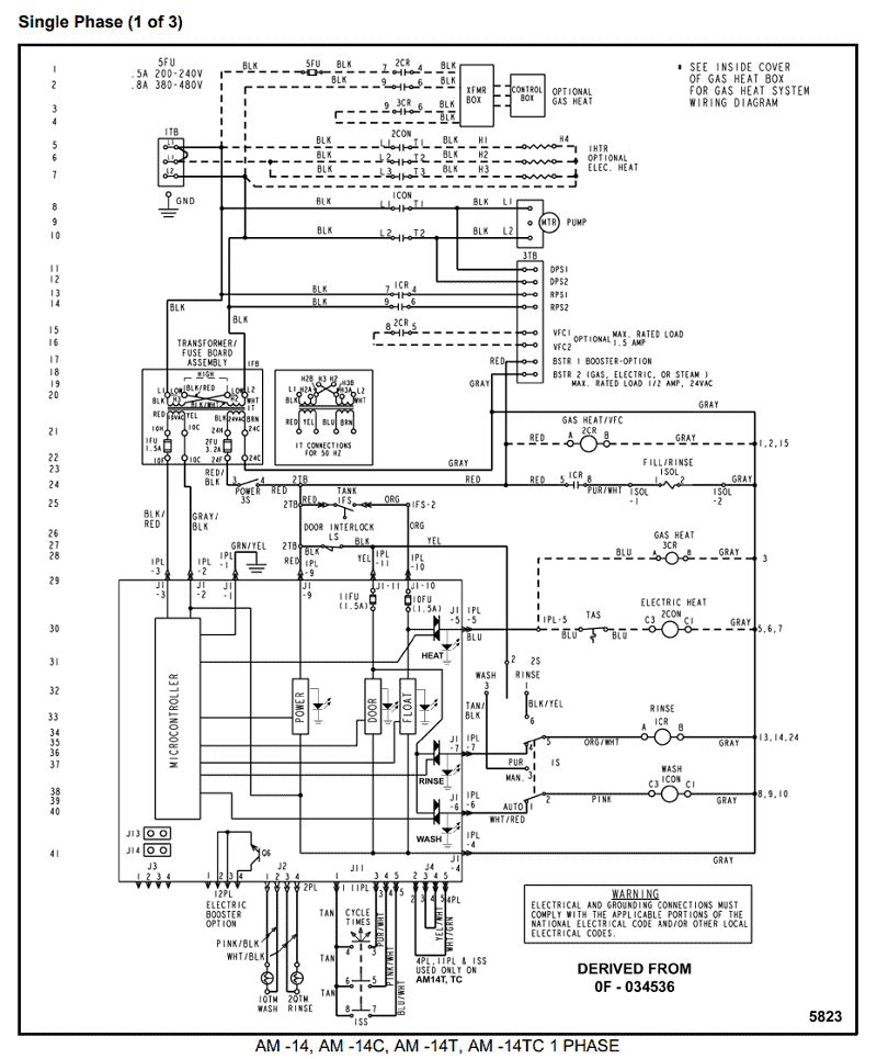
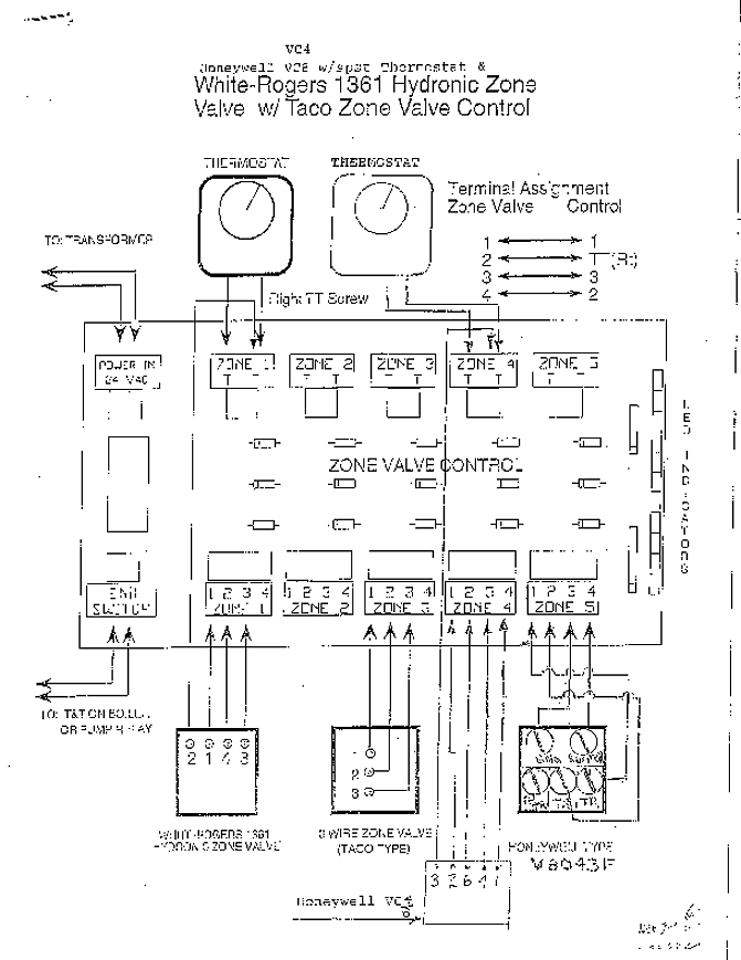
Short-circuit shutdown feature with automatic restart. • With soft start Wiring diagrams and installation examples, page 2.
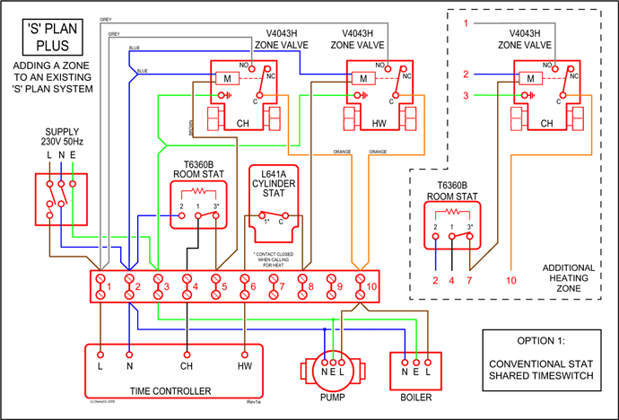
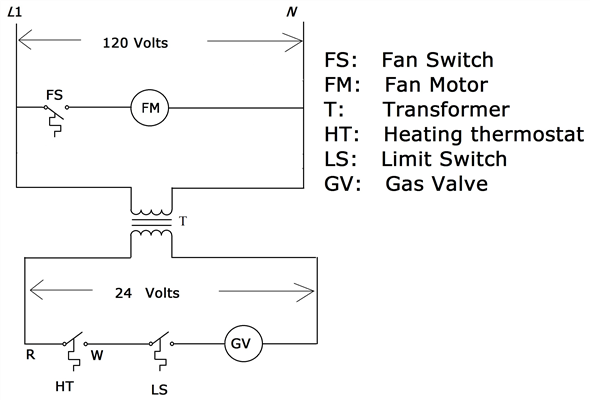
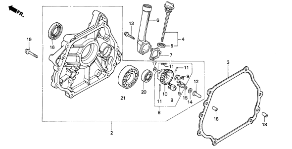
TE-U 1 10 V sc, 20 – VA ATCO Balmoral 17S (F) Parts Diagram Select a page from the ATCO Balmoral 17S diagram to view the parts list and exploded view diagram. The following operating manuals can be downloaded in PDF format: Manual Title ; atcopdf: Atco Atco pdf. Wiring with one lamp configuration Pic 2. Wiring with two lamp configuration (Atco PC T5 Pro ballasts.) Wiring for switch dim Pic.

3. Wiring with 4 core flex Pic 4.
Wiring with 5 core flex Pic. 5.
SwitchDIM with one operation point DSI and Dali wiring diagram with 5 core flex. Created Date. Oct 24, · I am currently studying replacing my 12V halogen downlights with LEDs.

I have about 35 in the house. I have identified my transformaers as ATCO TM safety isolating Transformers which are stated as suitable to drive low loads such as schematron.org not switch mode. The electronic transformers tested were: Tridonic Atco Possum, PoweRun Model No.
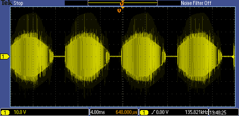
, OSRAM Redback and a Tridonic Atco speedy. Their specified load requirements were A, W, W and A, respectively.

An Atco TM wire wound transformer was used for comparison.LEDBenchmark – 12V Transformers and LED CompatibilityLEDBenchmark – Transformers for MR16 LEDs