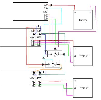
Use relay output R1 set to operating state Fault to switch Off the product once an error is detected. A1: Drive. KM1: Contactor. Control Block Wiring Diagram.
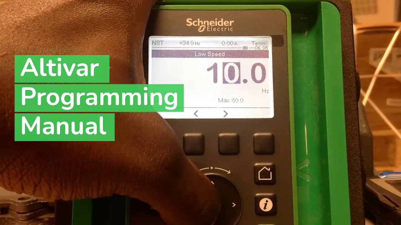
(1). Variable Speed Drives ATV, ATV Installation Manual .
Specific Wiring Instructions For Wall Mounting Drives. Wiring Diagrams.

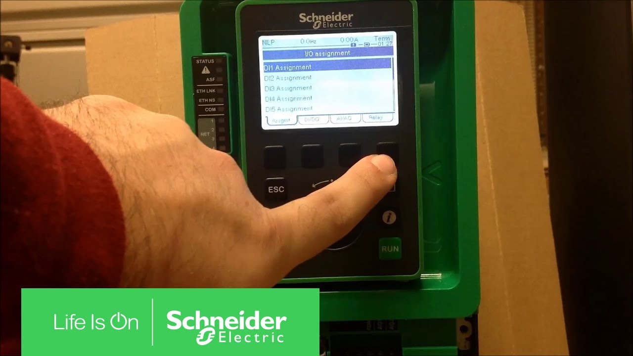
Download: 2) ATV/ Installation manual – Altivar Process ATV Altivar Process ATV, ATV Installation manual .. NOTE: This diagram is an wiring configuration using DI1 assigned to forward operation.

(1) Line chokes . Specific Wiring Instructions For Wall Mounting Drives.

Wiring Diagrams. ..
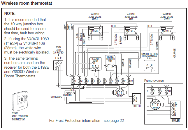
EAV (English). ATV, ATV Installation Manual.Drive systems may perform unexpected movements because of incorrect wiring, incorrect settings, incorrect data or other errors.

zCarefully install the wiring in accordance with the EMC requirements. zDo not operate the product with unknown or unsuitable settings or data. zPerform a comprehensive commissioning test.

Browse Altivar Process in the Schneider Electric catalog including Item #,Voltage Rating,Enclosure Rating,Control Voltage,Digital Inputs,Analog Inputs,Analog Outputs,CAD Drawings. ATVU75N4 – variable speed drive ATV – kW/10HP – V – IP21/UL type 1.
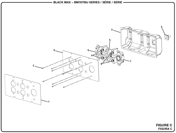
Products. View the new All Products menu. View the new All Products menu.
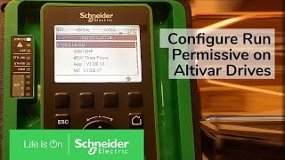
Looking for product documents or software? Go to our Download Center. Residential and Small Business.
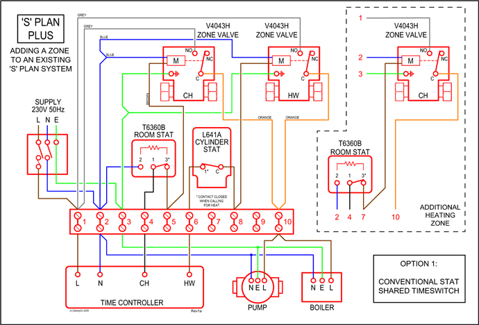
Electrical Car Charging. Feb 14, · Tutorial for configuring Altivar ATV & ATV Process Drives for 3 wire control to operate DI1 (normally closed) as stop button and DI2 (normally open) as start button. We would like to show you a description here but the site won’t allow us.ATVC31N4 – variable speed drive ATV – kW/HP – V – IP00 | ScVariable Frequency Drives Wiring Diagram – Electrical Schematic
