When dealing with the electrical connections in heating systems, it’s crucial to understand the exact placement of wires to avoid malfunction or damage. The first step is identifying each terminal and its corresponding function. Ensure all connections are securely fastened and free of corrosion to maintain efficient operation.
Begin by verifying the power source connections, as improper voltage can lead to system failure. Use a multimeter to check continuity before making any adjustments. Additionally, make sure all grounding points are properly connected to prevent electrical hazards.
For safe and effective performance, use only the specified gauge of wire recommended for each component. Overloaded circuits can cause overheating and even fire risks. When linking different parts of the system, always double-check the manufacturer’s specifications for wire placement and terminal identification.
Test the system after installation by turning on the power and observing the operation of each part. Look for any signs of irregularities such as excessive heat or malfunctioning components. If any issues arise, recheck your connections or consider consulting an expert for further assistance.
By following these straightforward steps, you can ensure a reliable and safe electrical setup for your heating equipment, minimizing the risk of future complications.
Understanding the Electrical Layout for Your Heating System
To ensure proper operation of your heating unit, follow these crucial steps:
- Confirm the power supply matches the required voltage and current specifications.
- Check all connections, ensuring each terminal is tightly secured to prevent electrical arcing.
- Verify the continuity of wires to avoid any interruptions in current flow.
- Examine the transformer for any signs of malfunction, such as burn marks or unusual noise.
For troubleshooting, consider the following common issues:
- If the heating element is not activating, inspect the control board for faulty relays or blown fuses.
- In case of irregular operation, test the thermostat and temperature sensors for accurate readings.
- Ensure the ground wire is correctly connected to prevent electrical hazards.
Finally, always replace damaged or outdated components with parts that meet or exceed the original specifications to maintain optimal performance.
How to Identify Key Components in an Atwood Furnace Wiring Diagram

Start by locating the power supply terminals. These are the entry points for electrical current into the system. Usually marked with L and N symbols, these connections will be your reference for any troubleshooting involving voltage or current.
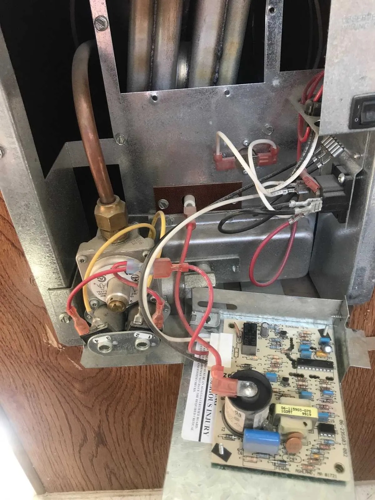
Next, focus on the control board, often situated centrally in the schematic. This is where the main control signals are processed, and connections to safety devices, sensors, and relays will originate. The board is typically marked with pins labeled for various components like the fan motor, thermostat, or flame sensor.
Identify the transformer in the diagram. This component is responsible for stepping down the incoming voltage to a lower level. It is critical to ensure it is properly connected to the control board and safety switches. Look for clear labels such as 24V or 12V next to its wiring.
The ignition system is another crucial element. In the schematic, you’ll often find it connected directly to the control board or a dedicated relay. Check for a clear path leading to either a spark electrode or glow plug depending on the system type. This will help confirm proper operation during the heating cycle.
Look for sensor connections, especially the thermocouple and flame sensor. These components are usually linked to the control board and play a role in detecting flame presence. Broken connections here could cause safety issues, so double-check these parts for accuracy and continuity.
Finally, inspect the fan motor wiring. The fan is crucial for air circulation and is typically linked to a relay or a switch. Ensure the wiring from the motor to the control board is intact and correctly routed to avoid overheating or malfunction.
Step-by-Step Guide to Troubleshooting Electrical Issues in Heating Systems

1. Verify Power Supply: Ensure the unit is receiving power. Check the circuit breaker and fuses to confirm there are no interruptions. If the breaker is tripped, reset it and inspect for any damage or short circuits.
2. Inspect Connections: Examine all terminals and connectors for loose or corroded parts. Tighten any exposed or compromised terminals. Use dielectric grease to prevent future corrosion.
3. Test the Control Board: The control board can malfunction due to power surges or age. Use a multimeter to test the continuity of components. If readings show inconsistencies, replacing the board may be necessary.
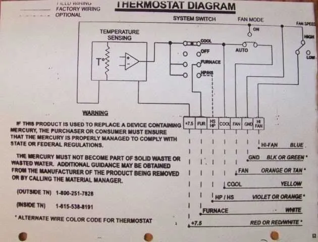
4. Check for Continuity in Thermostat Circuit: Disconnect the thermostat and test it for continuity. If there is no continuity, the thermostat may need replacing. Ensure the wires leading to the thermostat are intact and free from damage.
5. Examine the Ignition System: Ensure the ignition module is functioning properly by checking for a spark. If there is no spark, inspect the igniter and the wiring leading to it. Replace any faulty components as needed.
6. Inspect Safety Switches: Safety switches, including limit and pressure switches, often shut down the system in case of malfunction. Test these switches for proper operation using a multimeter. If they are not functioning, replace them immediately.
7. Look for Short Circuits: Use a multimeter to check for shorts between the wiring and ground. If a short is detected, identify the damaged section of wire and repair or replace it.
8. Test the Motor and Capacitor: If the motor fails to start, check the capacitor for signs of failure, such as bulging or leaking. Test both components with a multimeter to ensure proper function. Replace as necessary.
9. Reset the System: After completing all tests and repairs, reset the unit to ensure all functions return to normal. This may require turning the power off and on again or following the manufacturer’s specific reset instructions.
Understanding the Color Codes and Circuit Connections in Heater Schematics

Red wires typically indicate power supply lines, carrying voltage to various components. These should be connected directly to the positive terminal of the power source, ensuring the system is energized correctly. When working with control units and relays, always verify the red connections are secure and intact before proceeding with any troubleshooting or maintenance.
Black wires are generally used for low-voltage circuits, particularly in switches and thermostats. These wires may connect to devices that regulate the operation of the heating system. Confirm that the black lines are connected to their respective terminals without any breaks or signs of wear.
White wires are commonly employed as neutral connections. They act as return lines, completing the circuit by carrying current back from the components to the power supply. Ensure these are connected correctly to prevent short circuits and ensure proper function.
Green or bare copper wires should always be linked to ground connections. These are essential for safety, directing excess electricity safely to the earth to avoid potential hazards such as electrical shocks or fire. Never overlook this grounding step during installation or repair work.
When working with connections involving capacitors or other components, be mindful of the specific placement of blue and yellow wires. These colors often correspond to specific features in the circuit, such as activating the ignition system or controlling airflow. Always follow the manufacturer’s guidelines to ensure proper functionality.
Double-check all connections and wire placements against the schematic before applying power. A simple error in wiring color placement could lead to system malfunctions, electrical shorts, or unsafe conditions.