If you are experiencing electrical issues in your 2008 model vehicle, knowing the exact layout of its power distribution center can save you time and hassle. Each relay and connection serves a crucial function in maintaining the proper operation of various components in the car. A complete understanding of how the power is routed through the circuits is essential for diagnosing problems accurately.
The main power panel is located in the cabin, beneath the dashboard. This unit controls vital functions such as lighting, airbags, and entertainment systems. In addition to the cabin unit, there’s another critical power distributor under the hood that handles functions like the engine control and air conditioning.
When troubleshooting electrical issues, always begin by checking the primary fuses associated with the malfunctioning system. For example, if the dashboard lights or wipers aren’t working, inspect the related circuits in the panel. Each fuse is clearly labeled according to its specific function, ensuring a straightforward inspection and replacement process.
For precise identification, it’s advisable to consult the detailed map of the system, ensuring you can track which fuse corresponds to each component. This will not only help in quickly pinpointing the problem but also avoid unnecessary replacements of fuses that are still functional.
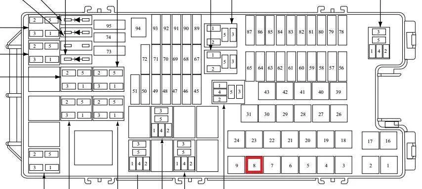
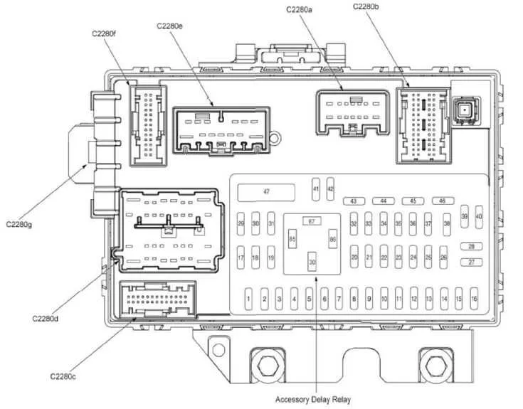
08 Ford Edge Electrical Component Layout

Refer to the electrical component layout for accurate fuse placement. The main power distribution panel under the hood contains fuses for critical systems like the engine control unit, headlights, and air conditioning. Inside the cabin, another set of circuits controls interior features such as the audio system, climate control, and safety sensors. Each fuse is clearly numbered for easy identification, with a label indicating the function it serves. Make sure to replace any blown units with the correct amperage rating as indicated on the cover to avoid damage to the circuits.
The engine compartment panel is accessible by lifting the hood. In the passenger area, check beneath the dashboard on the driver’s side for the secondary panel. Always use a fuse puller to prevent damage when replacing or checking the condition of any fuse. Keep spare fuses in the glove compartment to ensure you’re prepared for emergencies.
If a particular feature stops functioning, start by checking the corresponding circuit in the panel. For complex issues, a more detailed inspection of the wiring might be needed. Always consult the manufacturer’s manual for further specifications on the layout and function of each individual component in the system.
Locating the Power Distribution Areas in the 2008 Vehicle
The main power distribution areas are located in two specific regions of the vehicle: the engine compartment and inside the cabin.
- Under the Hood: The primary power center is positioned near the driver’s side, adjacent to the engine. It’s housed within a large rectangular unit that can be accessed by releasing a latch.
- Interior Cabin: Another key location is below the dashboard on the driver’s side, typically around the left kick panel. This area can be accessed by removing a small cover or panel.
Both of these areas contain multiple sections for different electrical components and should be carefully inspected when diagnosing issues. Ensure the vehicle is powered off before accessing either area for safety.
Identifying Key Fuses for Critical Systems in the 08 Ford Edge

Start by locating the central electrical panel, typically near the driver’s side of the cabin or under the hood, to ensure proper functionality of essential vehicle systems. Focus on the components responsible for power distribution to the engine management, air conditioning, and safety features like airbags and anti-lock braking system (ABS).
The primary circuit for the engine control module (ECM) is commonly linked to a 15A or 20A circuit. For air conditioning, check the specific relay dedicated to climate control–this may be found in the central area of the system and could be a 10A or 15A link. The security system, including the ignition system, is generally powered by a dedicated 30A or 40A module, often in a visible position for easy access.
For critical safety equipment, such as airbags, verify the 10A fuse typically dedicated to this system, which should be listed in the vehicle manual for precise location. Also, ensure that the ABS system is connected to a robust 30A fuse, often placed centrally, for uninterrupted operation of the braking system.
It’s essential to inspect the lighting circuits, including headlights and tail lamps, which can be powered through circuits ranging from 10A to 15A depending on the configuration. Also, be aware of the wiper motor circuits, generally protected by 20A circuits for optimal functionality.
To maintain operational integrity, always verify the continuity of the fuse link by testing with a multimeter, replacing blown connections with the exact rating specified to prevent any electrical malfunctions. Familiarize yourself with the specific labeling and color-coding used to identify these crucial power systems for smooth and uninterrupted driving performance.
Step-by-Step Guide to Replacing Fuses in the 08 Ford Edge

1. Locate the electrical panel: Start by identifying the location of the central electrical panel, which is generally found on the driver’s side near the dashboard. Some models might have an additional panel under the hood. Make sure the vehicle is powered off before proceeding.
2. Open the compartment: Use the latch or lever to open the panel cover. For some units, there may be screws securing the cover. In that case, a screwdriver will be required to remove them.
3. Identify the damaged component: Check the label inside the cover to pinpoint the specific location of the malfunctioning part. Each section should be labeled with the corresponding function. Make sure the issue lies with one of these components before moving forward.
4. Use appropriate tools: Prepare a small pair of needle-nose pliers or a dedicated tool for safe removal. These are ideal for gripping and extracting the component without damaging the surrounding components.
5. Remove the faulty part: Gently pull out the malfunctioning part using the tool. Ensure that it is entirely removed without forcing it, as this could break the housing or wiring.
6. Check the replacement: Verify that the new part matches the old one in size and amperage rating. Using a component with the wrong specifications could lead to electrical malfunctions or even damage.
7. Install the new part: Insert the replacement carefully, making sure it fits snugly into its designated slot. Press firmly, ensuring that the component locks into place without any gaps.
8. Test the system: Turn on the vehicle and check if the issue has been resolved. If the problem persists, recheck the connections or inspect for any underlying issues not related to the component.
9. Close the compartment: Once the installation is complete, close the panel securely and ensure that no tools or debris remain inside.