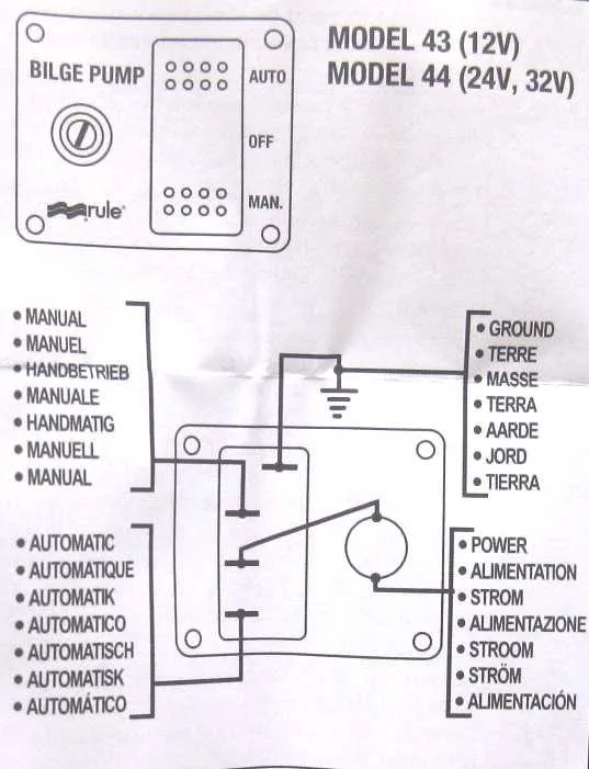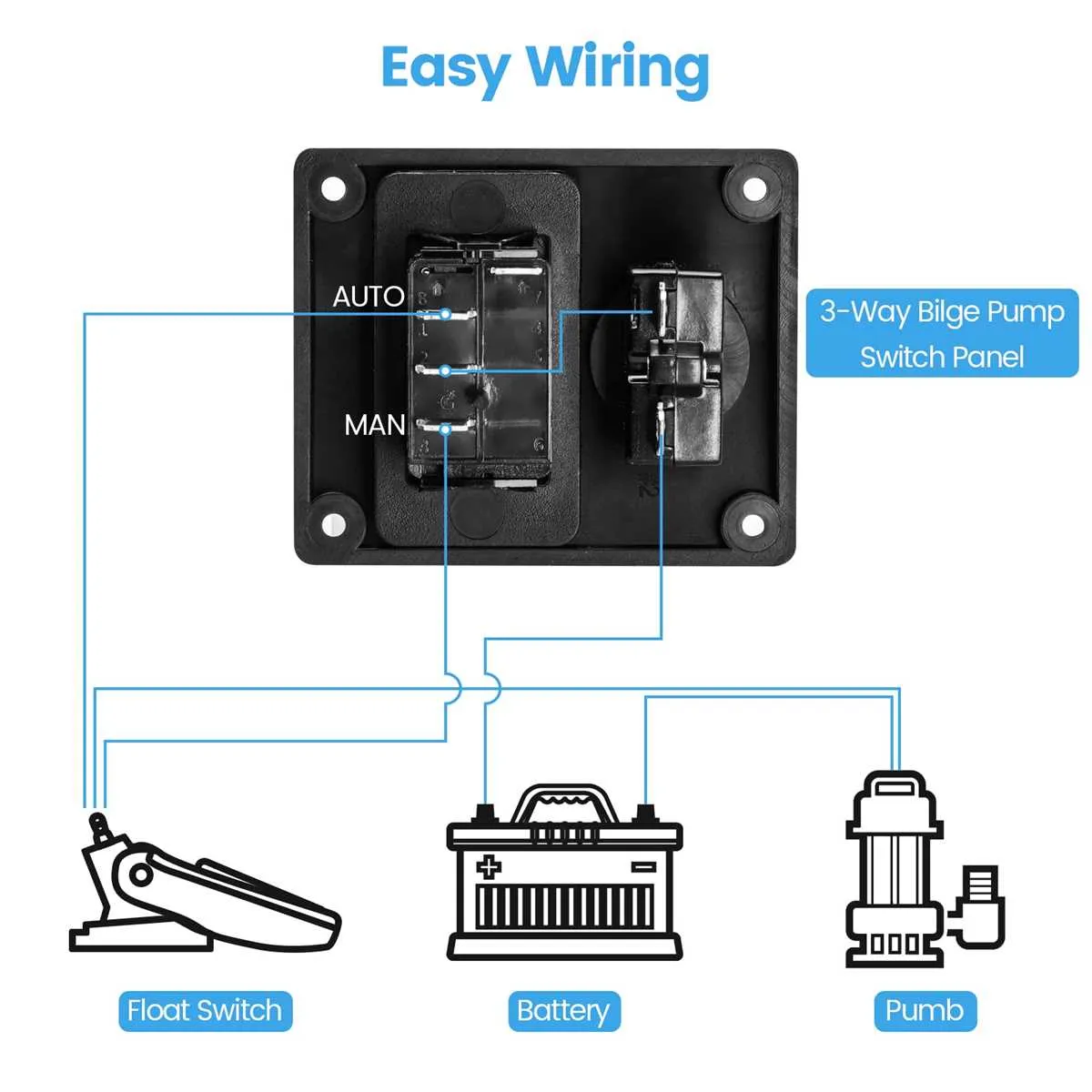
For optimal water removal in a vessel’s lower compartments, a three-conductor setup is essential. Connect the positive lead of the power supply directly to the float switch’s input terminal, ensuring it receives continuous energy. Then, connect the output terminal of the float switch to the energizing terminal of the expulsion unit’s motor. Ground the negative lead from the power supply to the chassis, maintaining a secure connection to complete the circuit.
When incorporating a manual override switch, route the positive lead from the power source to a terminal on the manual switch, then link it to the motor’s energizing terminal. This ensures the expulsion system can operate even if the float mechanism fails or is bypassed. Use appropriately rated fuses in both automatic and manual lines to protect from potential electrical surges or failures.
For safety and efficiency, utilize tinned copper conductors with marine-grade insulation, capable of withstanding moisture and corrosion. Ensure all connections are crimped with watertight terminals and secured with heat-shrink tubing to prevent exposure to saltwater. Secure the conductors along the hull with clips every 18 inches, avoiding sharp bends or kinks that could stress the insulation or cores.
Check the float activation mechanism periodically for debris or wear, ensuring reliable operation. Additionally, confirm the proper functioning of the manual switch to maintain emergency capability in critical situations.
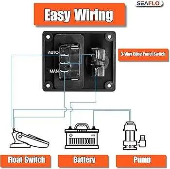
3-Line Marine Fluid Displacement Setup Schematic

Begin by connecting the brown lead to the positive terminal of the power source through a dedicated fuse. The brown with white stripe conductor links to the manual switch, routed from the positive side of the switch to the primary load. The black conductor connects directly to the ground or negative terminal of the power source. Maintain a separation between the automatic activation pathway and the manual control line to ensure seamless operation. Secure all connections using marine-grade crimp connectors and heat-shrink tubing for optimal insulation. Confirm the functionality by energizing the system and verifying both automatic fluid extraction and manual activation via the toggle switch.
Power Source Connection and Circuit Protection

Connect the red lead directly to the positive terminal of the battery through a 3-amp inline fuse to safeguard against shorts and overloads.
Use marine-grade connectors and heat shrink tubing to ensure a corrosion-resistant and watertight joint.
- Attach a 14 AWG marine-grade cable to the fuse holder and secure with crimped terminals.
- Link the negative side with a black lead directly to the negative battery terminal or ground block.
- Verify the connection with a multimeter; ensure no voltage drop under load.
- Secure cables along their route with clamps every 18 inches to prevent chafing.
- Incorporate a manual shutoff switch rated for the current draw to isolate the system during maintenance.
Choose circuit protection devices like resettable breakers or inline fuses rated for 1.5 times the maximum load current to handle startup surges.
Ensure the fuse holder is mounted above the highest possible water level to prevent corrosion.
Float Switch Integration and Configuration

Connect the float mechanism’s ground lead directly to the vessel’s negative terminal to ensure a reliable return path. Route the positive connection from the float to the load circuit’s positive line, bypassing the control relay if one is used. Use a 14 AWG stranded conductor with marine-grade insulation for all leads to reduce resistance and prevent corrosion. Secure all connections with heat-shrink terminals to enhance durability.
Install the float sensor vertically, ensuring it sits level with the base to avoid false activation due to vessel movement. Place it at the lowest point of the compartment to trigger the switch at the earliest stage of fluid accumulation. Configure the activation threshold by adjusting the sensor’s mounting bracket or using a pre-calibrated float with a set trigger level. Apply a dielectric grease to contacts to maintain performance over time.
Integrate a fuse rated at 15 amps inline with the float’s power lead to protect against overcurrent conditions. Verify that the float switch’s mechanical action is unobstructed and test the system with a controlled fluid addition. Confirm the switch actuates cleanly and deactivates as intended before sealing connections with adhesive-lined heat shrink for a watertight finish.
Manual Override Switch Wiring Method
Connect the manual override switch directly to the positive terminal of the power source. Utilize a single-pole, double-throw (SPDT) switch for precise control over the float switch and manual activation. Use a dedicated line from the switch to the device motor input, ensuring proper load rating.
Incorporate a 3-amp inline fuse between the power source and the switch to safeguard against overcurrent. Employ marine-grade conductors for connections, ensuring secure terminal lugs and crimping for durability. Color-code all lines distinctly to identify manual control from automatic circuits.
Ensure the manual switch is mounted in an accessible, dry location with clear labeling. Use heat-shrink tubing on exposed conductor ends for added insulation. Confirm continuity and correct polarity using a multimeter before powering the system. Verify switch operation in both positions to ensure uninterrupted function.