
these instructions will also work for a B5 A4 with the same engine. harness to repair this issue, which will likely cost you over $1,!
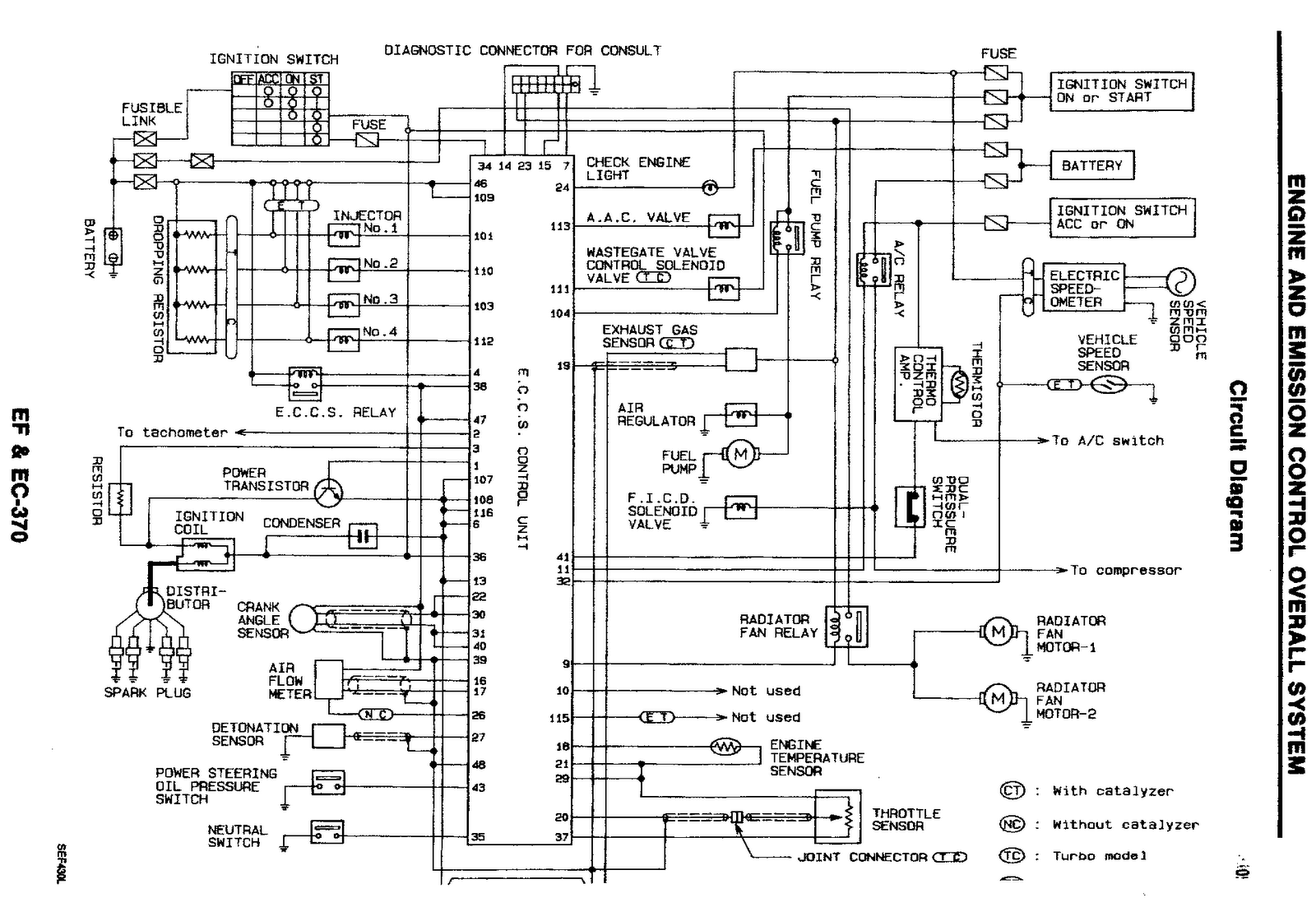
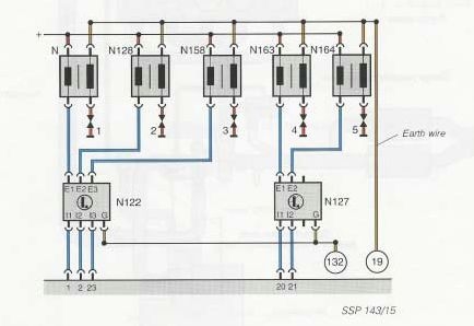
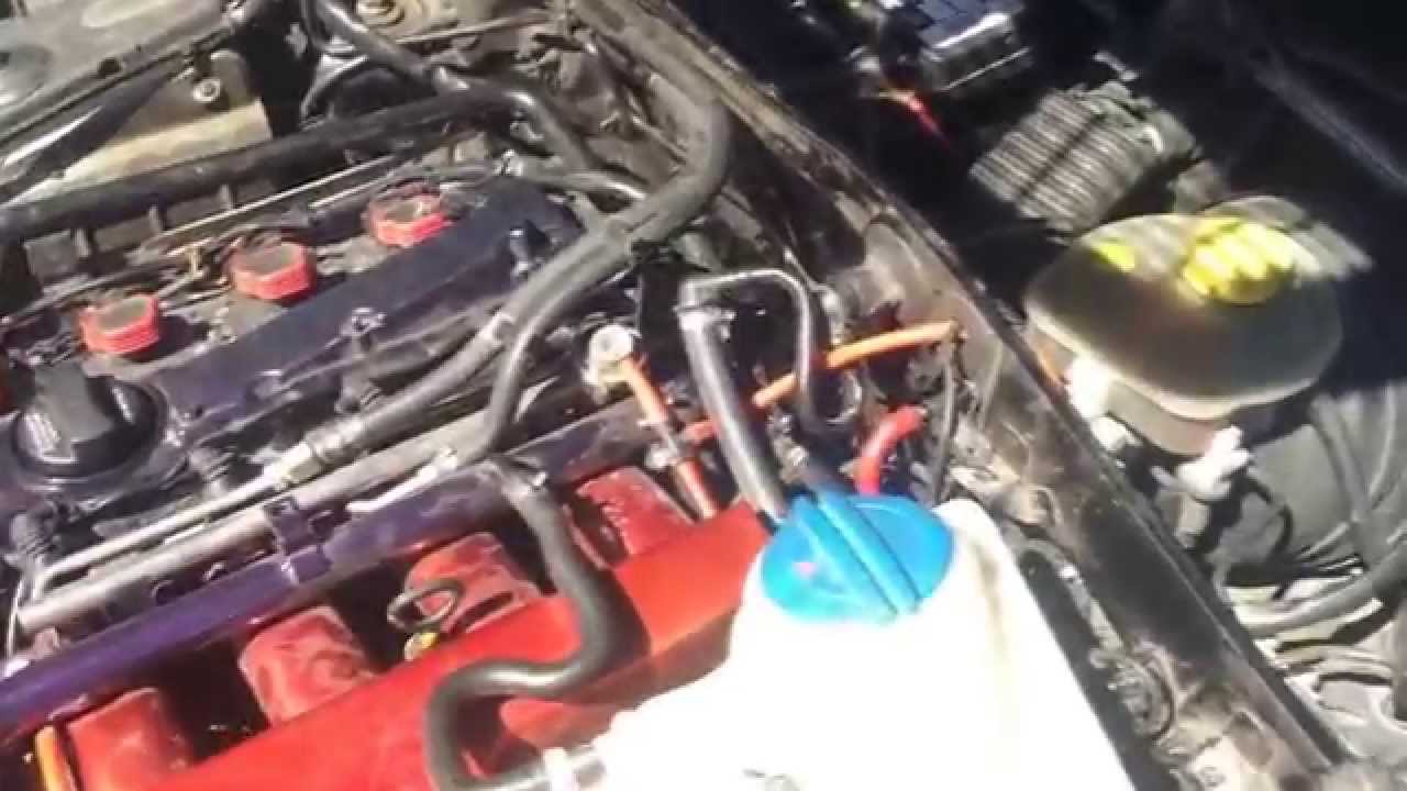
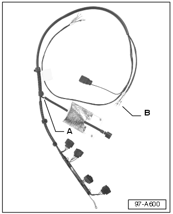
Our Ignition Wiring .. Release the locking tab on the top of each ignition coil connector, then slide the. Turn the ignition switch OFF and plug the 5-pin harness connector into the coil pack.
Click image to see an enlarged view. Fig.
On VR6 engines, the coil’s 5-pin . This ECS Coil Pack Harness Replacement Kit (Mfg#ecs01KT) fits Audi B5 A4 FWD T, Audi B5 A4 Quattro T, Audi B6 A4 FWD T, Audi B6 A4.
Now slip on a wire to each pin on the coil pack. That harness on ecs is 50$ plus shipping and its out of stock.
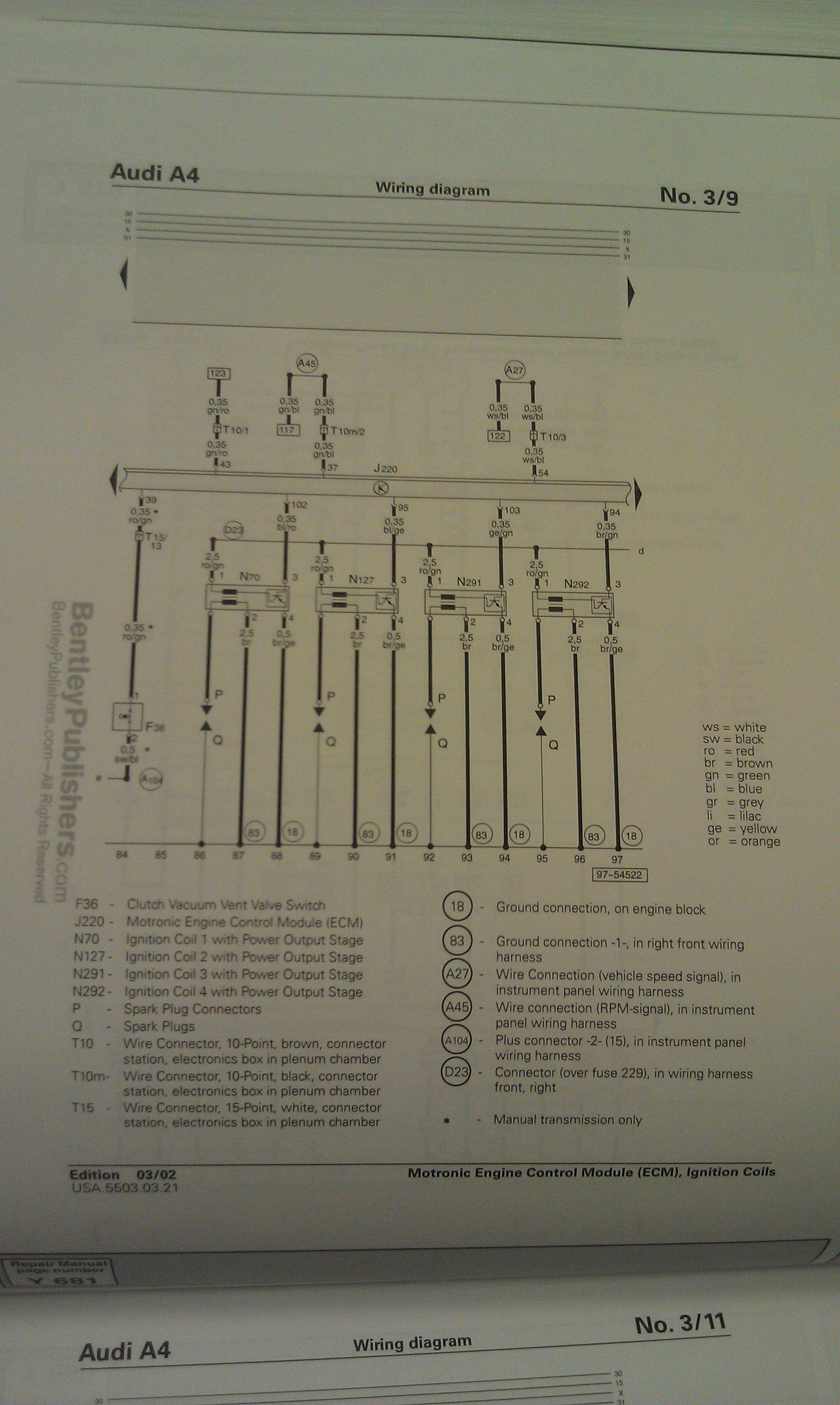
. Join Date: Oct 8th, ; Location: Warwick, RI; Posts: 4,; Vehicles: Bagged MK6 GLI, Boosted B5 A4. B5 Models Please discuss all – B5 A4 topics here.
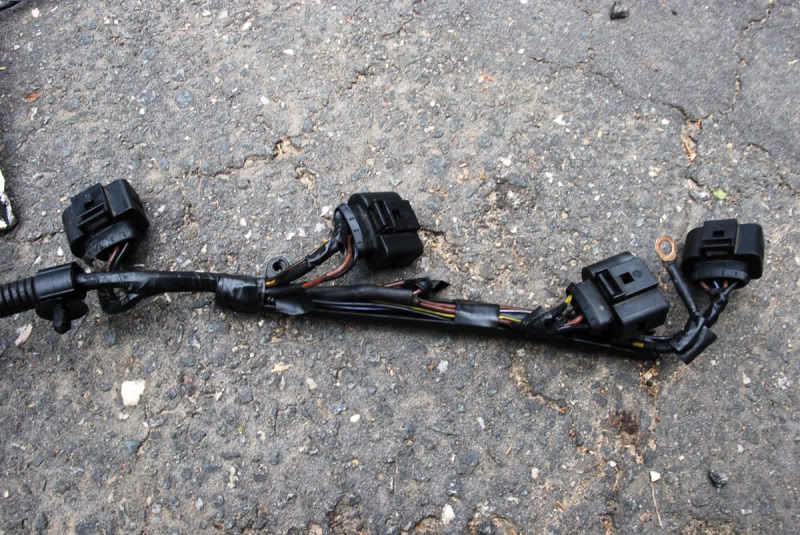
Broken coil pack connector housings are common causes of misfires. Splicing in new connectors can cause corroded wires and a messy wiring harness. Coil Pack Connector Housing with part number from Audi ( A4 AWM Code T).Brown Yellow / Green Blue Load L1 L2 L1 L2 1 2 3 1 – Yellow / Green 2 – Red / Black 3 – Red / White Load (metal housing only) Brown Blue Load L1 L2 Yellow / Green L1 L2 1.
Manitowoc QuietQube IBYC Manuals Manuals and User Guides for Manitowoc QuietQube IBYC. We have 1 Manitowoc QuietQube IBYC manual available for free PDF download: Technician’s Handbook. Manitowoc QuietQube IBYC Technician’s Handbook ( pages) Wiring Diagram Legend (EBTDR on the wiring diagram) could fail and weld the Normally Closed contacts closed.

The diagram below shows the correct wiring for GPH13 heat pumps. There are 3 wires that should be checked and corrected if necessary. The Purple (PU) wire should be connected to L2 on the contactor.
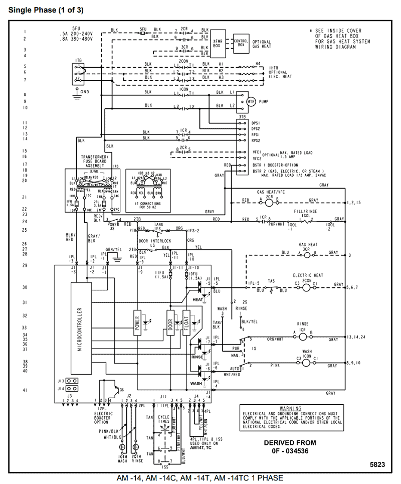
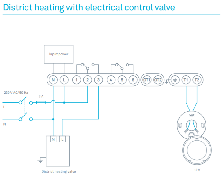
The black (BK) and red (RD) wires should be connected to L1. A wiring diagram is a simplified conventional pictorial representation of an electrical circuit. It shows the components of the circuit as simplified shapes, and the power and signal connections between the .
Installation & Field Wiring Guidelines Installation and Safety Guidelines 2–2 Installation & Field Wiring Guidelines DL High Speed Counter Interface Manual, 2nd Ed, Rev. A How to Install the Module The D2–CTRINT module must be installed in slot 0 next to the CPU.
.schematron.org – Coil Pack Wiring on an AEB – (DIY)Wiring diagram – Wikipedia