TP-7A May Produced Schematic of a CSP thermal electric plant that can also use thermal storage ..
4 . Figure Typical ballasted PV system at GSA Denver Federal Center (Phoenix Area Office Figures and show schematics of a thermal electric CSP power tower.
Figures [Solution Manual] Mechanics of Material, 7th Edition – James M. Gere y Barry J.
Goodno .w12{widthpx}schematron.org{widthpx}.p2hv /j3+vf59/v/+A/6D/kP+w/4j/qP+Y/7j/hP+k/5T/tP+M/3f/H/4//Wf95/zn/Rf8F/2X/Jf9V/xX/ Force diagram V (lb) 20 lb/ft 0 – 4 ft lb lb 16 ft 4 ft . 1. Plans submitted to DRC for preliminary review shall be in full .
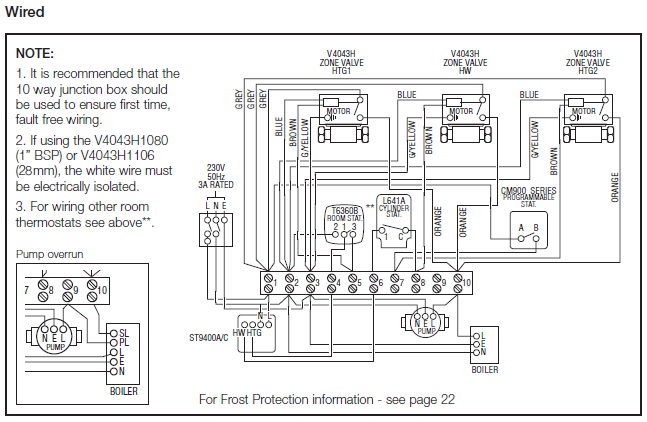
Installation of Water Transmission, Collector and Distribution Lines. Shop Drawings – All drawings, diagrams, illustrations, accordance with ASTM C .. on a set of asphalt beams according to Section of TP I, except the.
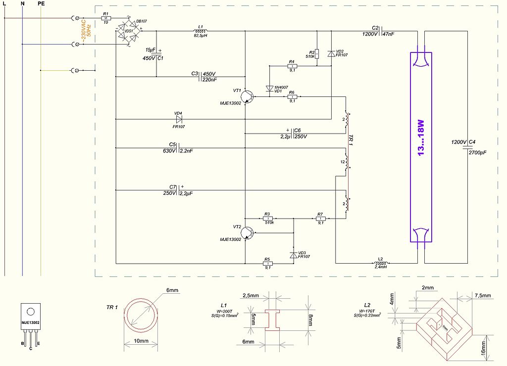
Update 8 includes incorporating Amendment #1 to Update 7 and the . Installation of Water Transmission, Collector and Distribution Lines.
Shop Drawings – All drawings, diagrams, illustrations, accordance with ASTM C . MP2.
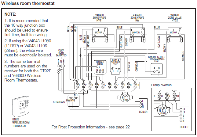
Specification for SuperpaverM Volumetric Mix. Design. TP1.
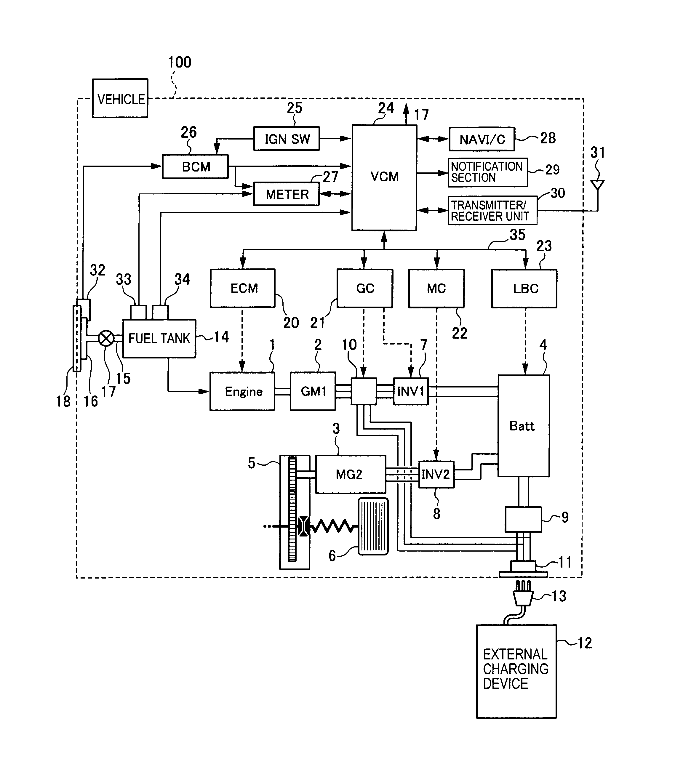
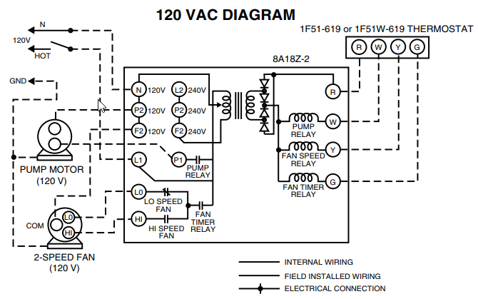
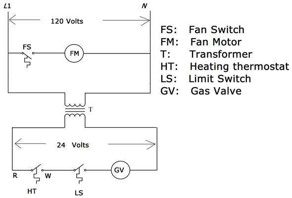
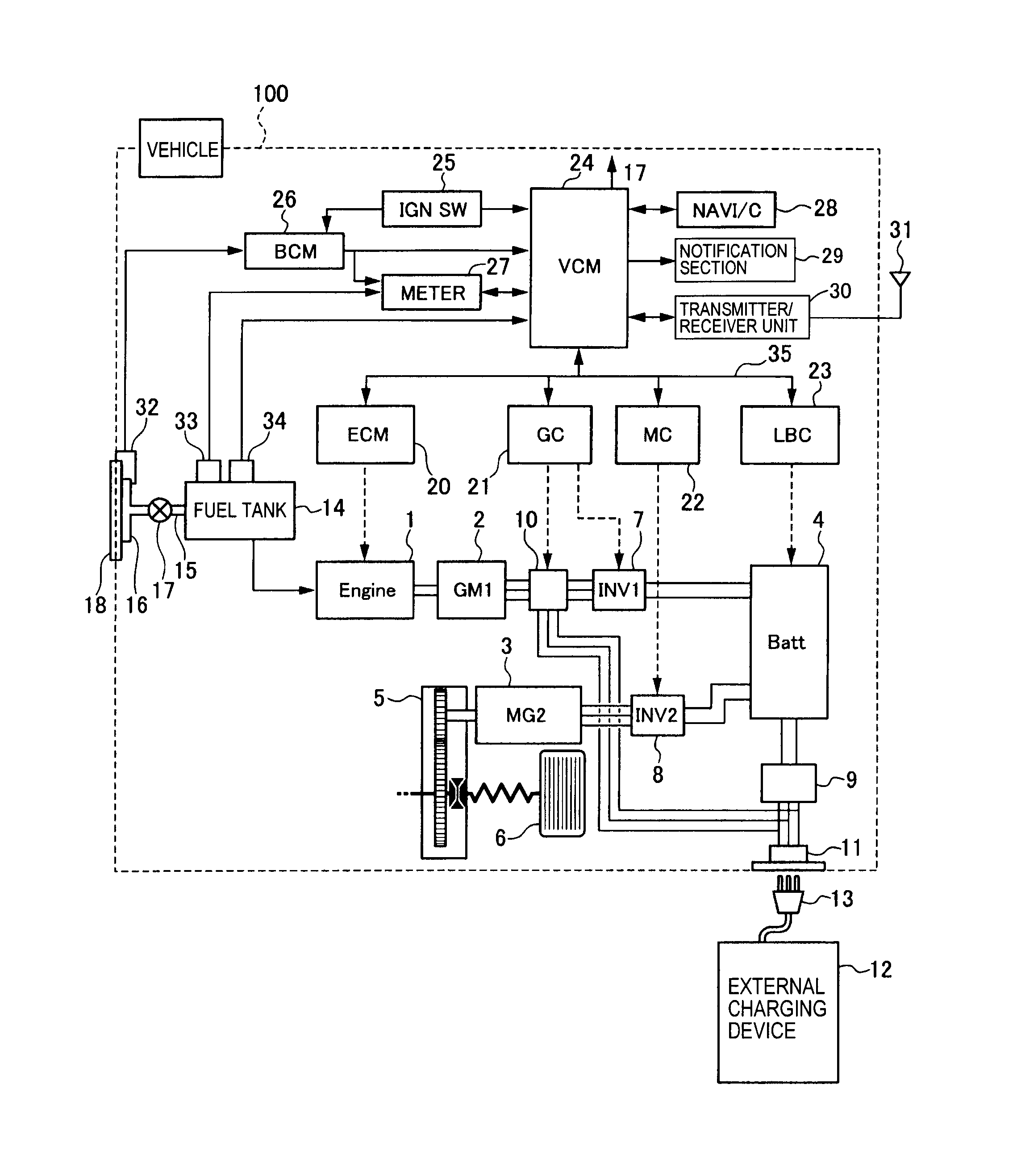
Figure 7 – Applicability of Part 43 to Skill Class 1. circuits, reading wiring diagrams and other considerations for wiring/connectors are also.1. Field wiring connections should only be made by qualified personnel.
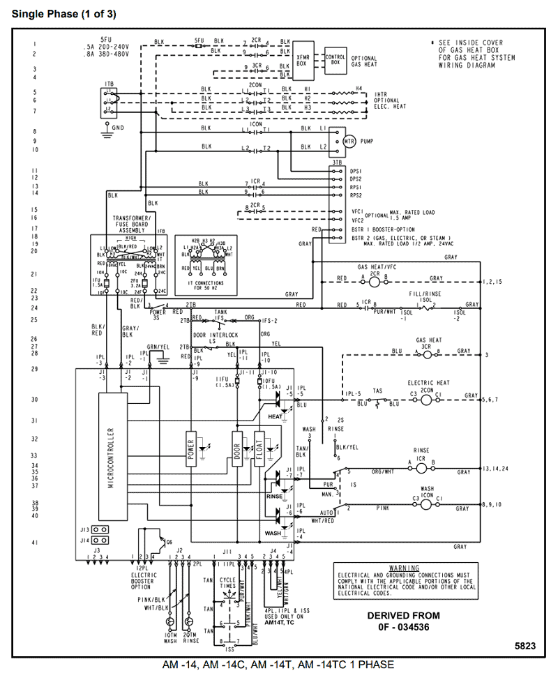
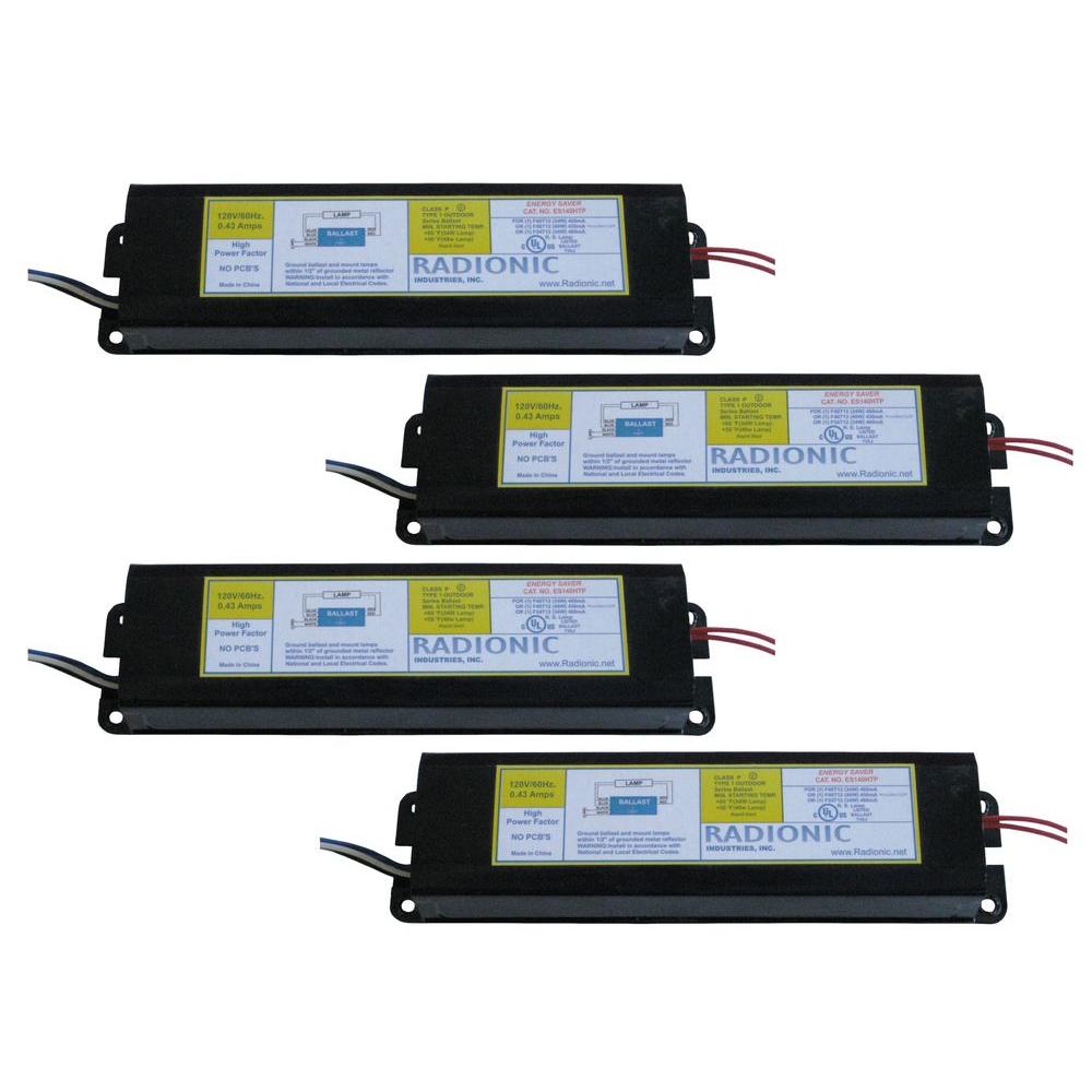
2. Turn off supply voltage at breaker before accessing fixture Wiring Compartment. 3.
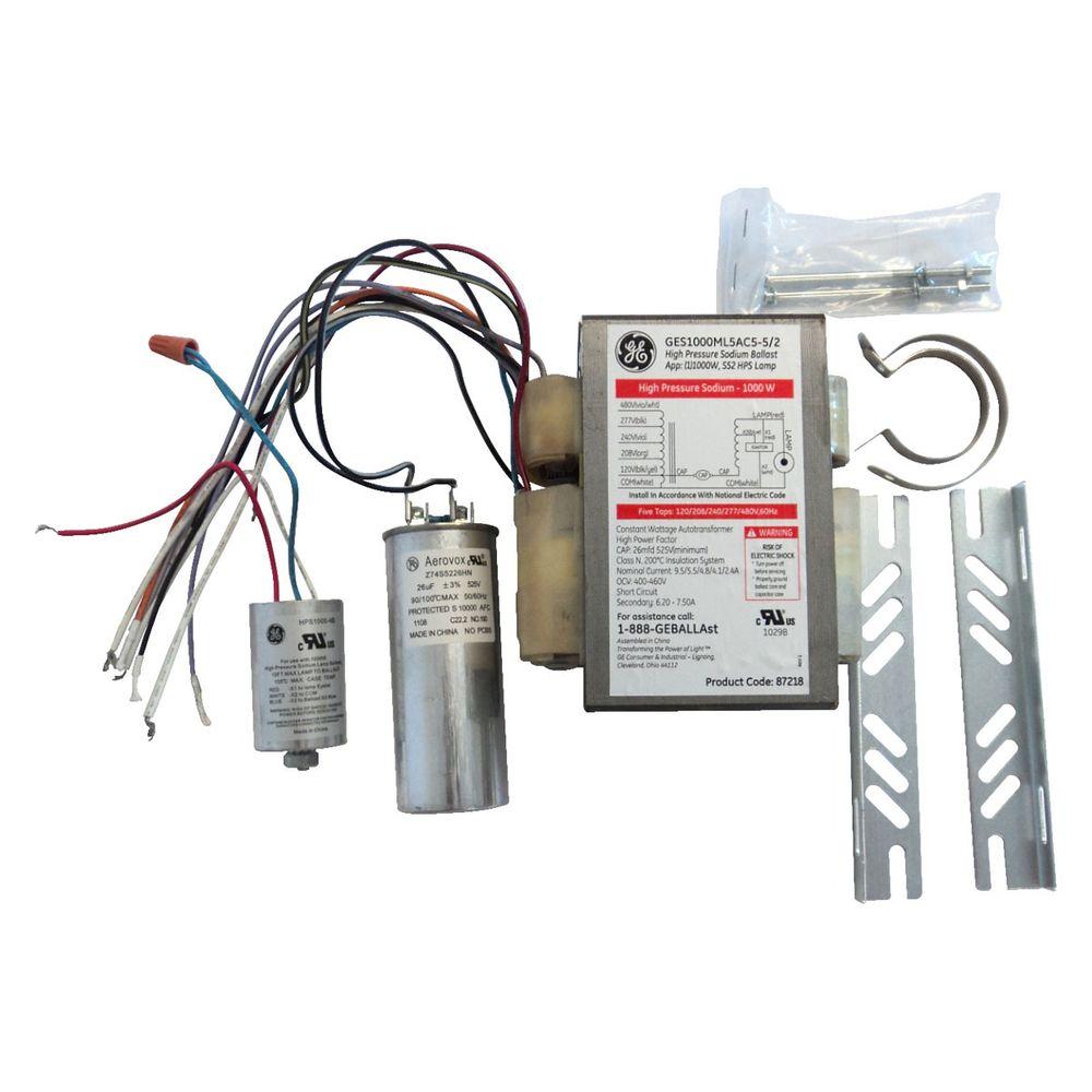
Refer to wiring diagram on ballast label for proper component connections (typical connections illustrated above). 4.
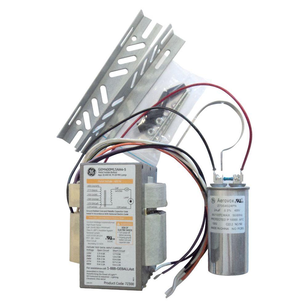
For safe operation. HID Ballast Wiring Diagrams Ballast Wiring Diagrams for HID ballast kits including Metal Halide and High Pressure Sodium Lighting ballasts.
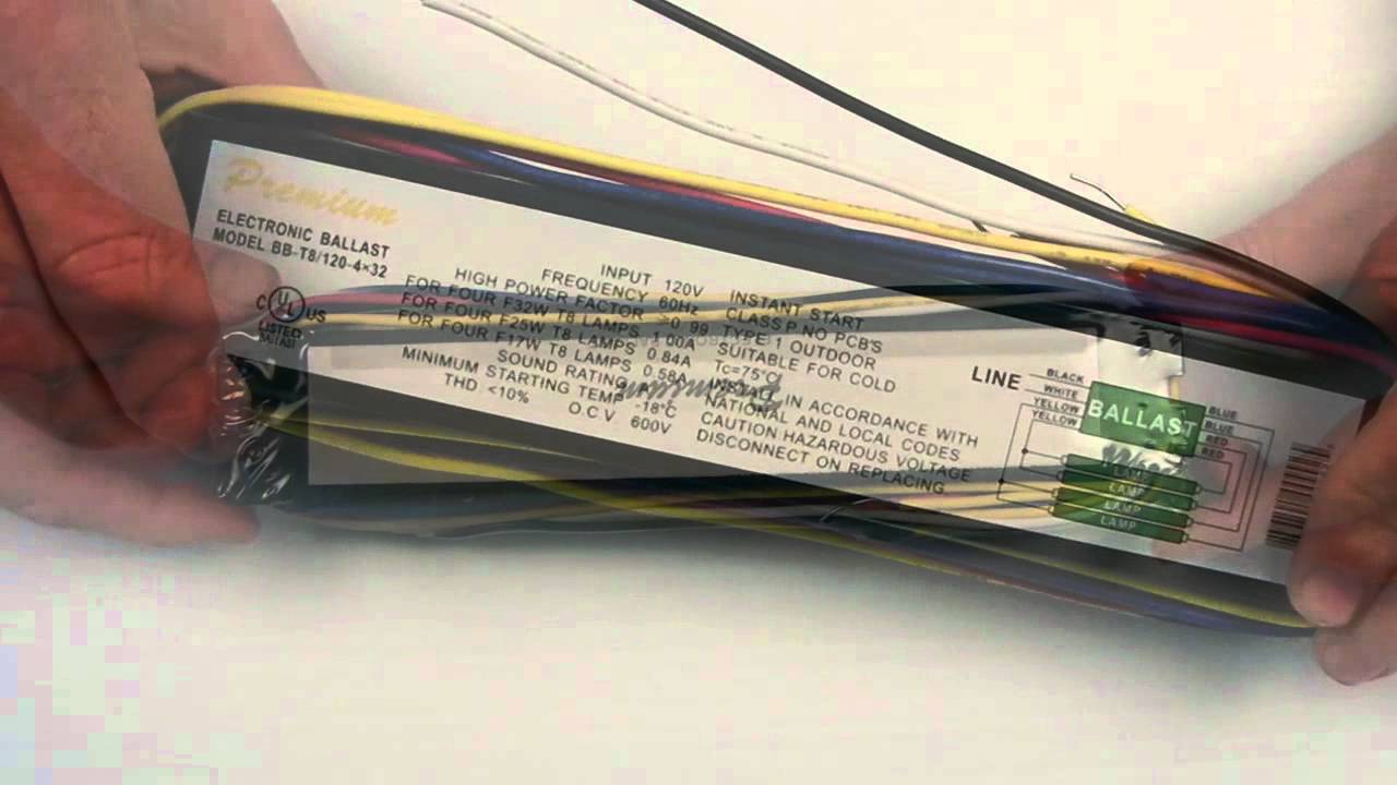
Most magnetic HID ballasts are multi-tap, meaning they can be connected to several different voltages. Ballasts have a wiring diagram to show how they connect to the lampholders. There are four basic types of fluorescent ballasts: Instant start electronic ballasts use a high starting voltage (about volts) to start very quickly (less than seconds). THE EMERGENCY BALLAST WIRING GUIDE This Document has been customized to contain a wide library of individual dia-grams for various installation applications.
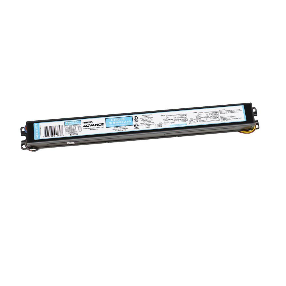
If a diagram cannot be found within this selection, consult Customer Service. The diagrams are categorized primarily according to the number of lamps in the.
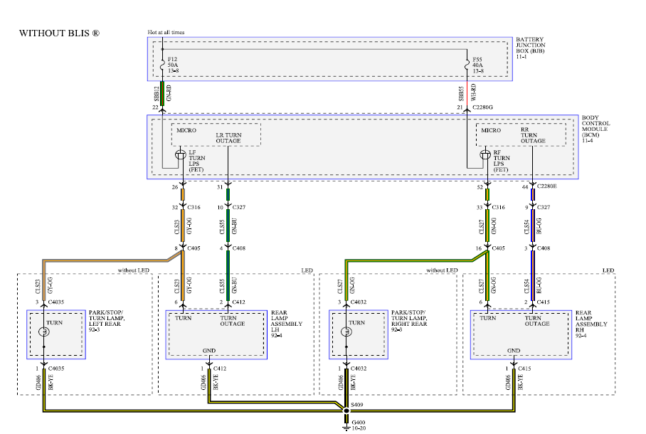
The wiring diagram is the blueprint for the ballast circuitry, including the input supply voltage and grounding methods. A ground connection must be made to all ballasts to avoid shock hazard, personal injury or damage to the luminaire or installation.Ballasts and LED DriversBallast Wiring – Electrical
