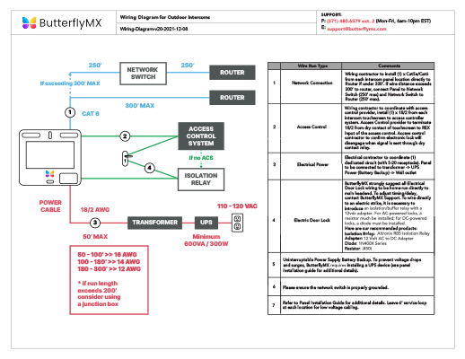
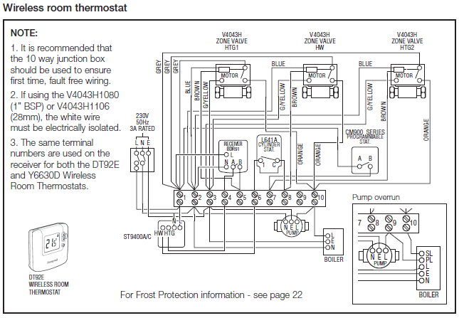
R & SE Wiring Diagrams. TECHNICAL NOTES. ○ To avoid ESD (Electro- Static Discharge) interfering with the operation of the keypad, ground the.

Waterproof Keypad. ASS & ASM Instructions. MOUNTING INSTRUCTIONS.
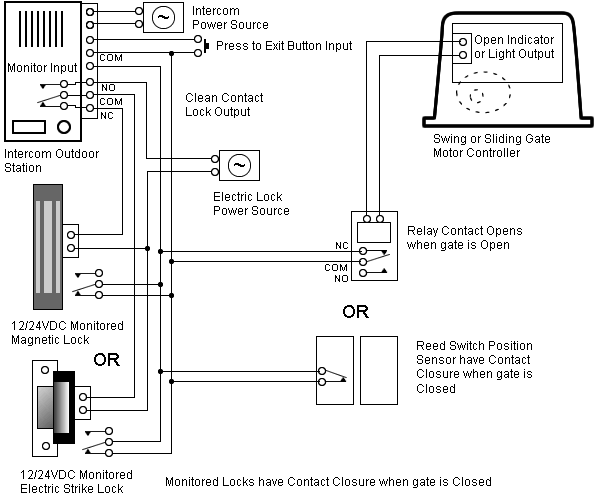
Connect keypad using wiring Diagram below. WIRING. EverSwitch piezoelectric Touch Metal technology for piezo switches keypads and control panels was the first commercially viable piezo switching technology.
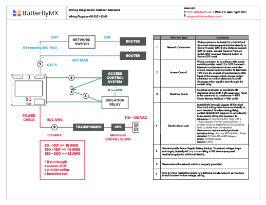
This manual is proprietary information of Software House. .. This chapter provides detailed RM-4 component diagrams, overviews the ..
Barantec. ▫ RSI.
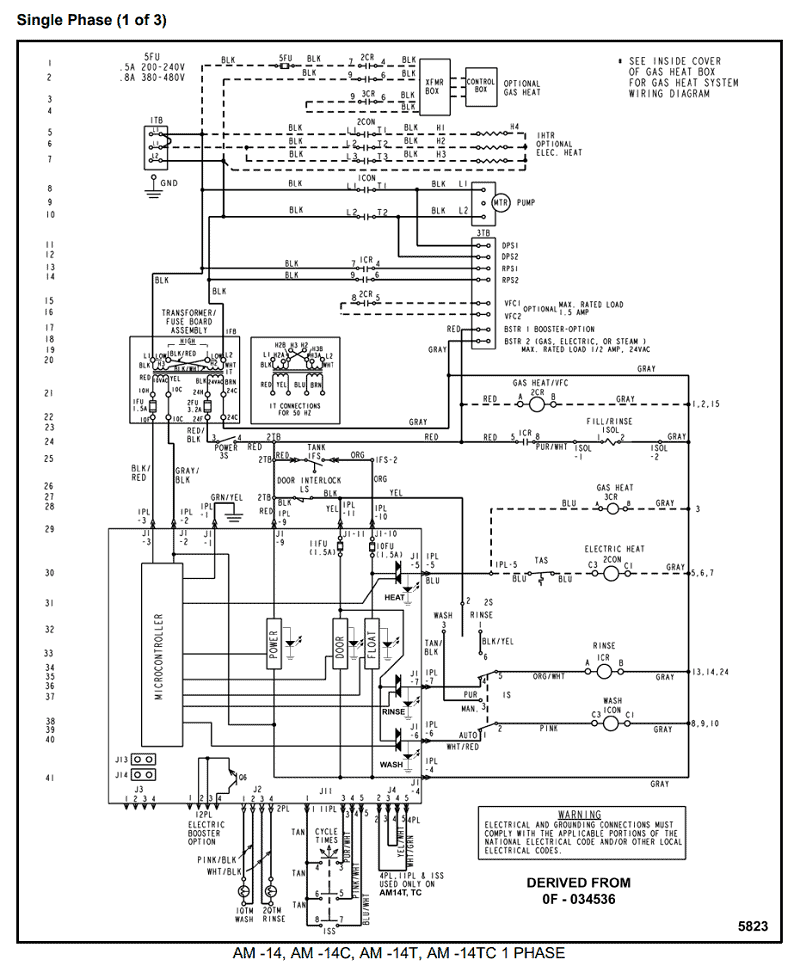
Refer to third party reader documentation for detailed information .. Keypad wiring.
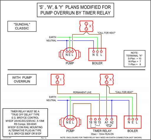
1. switches through to a variety of keypads and control panels to full size keyboards.
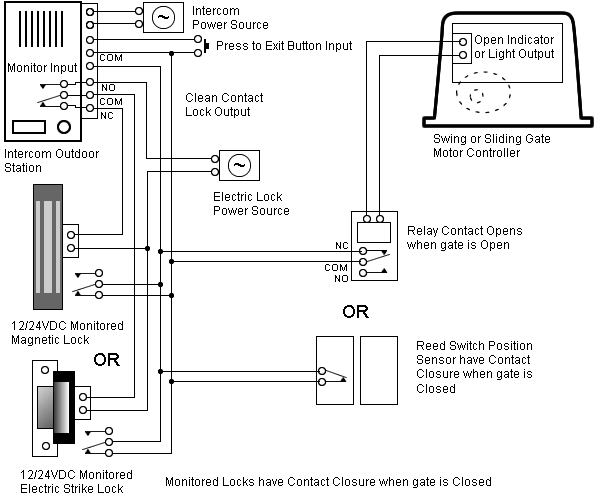
All products are Electrical Diagram. SMA1 .. Email: [email protected] diagram above shows how to connect two keypads to control a single door.
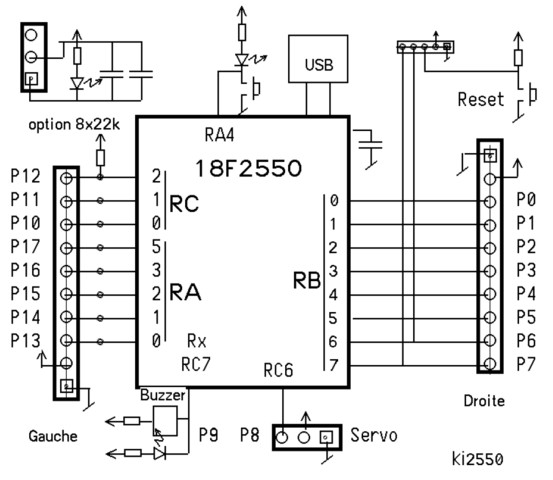
Entering your code on keypad 2 unlocks the maglock directly. When you enter your code on keypad 1, it triggers the REX input of keypad two, which unlocks the door Please note that user codes must be programmed into both keypads Rev 1 TECHNICAL NOTES. EverSwitch piezoelectric Touch Metal technology for piezo switches keypads and control panels was the first commercially viable piezo switching technology. When you do not use the A8GT-C05TK Numeric Keypad Panel connection cable, fabricate the connection cable in accordance with the following wiring diagram and parts list (max.

cable length: 20m ( feet)). (1) Wiring diagram Numeric Keypad Panel Connect shield to FG.
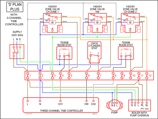
Wires for connection with external input power supply 12/24VDC Shield. Waterproof Keypad ASS & ASM Instructions MOUNTING INSTRUCTIONS Connect keypad using wiring Diagram below.
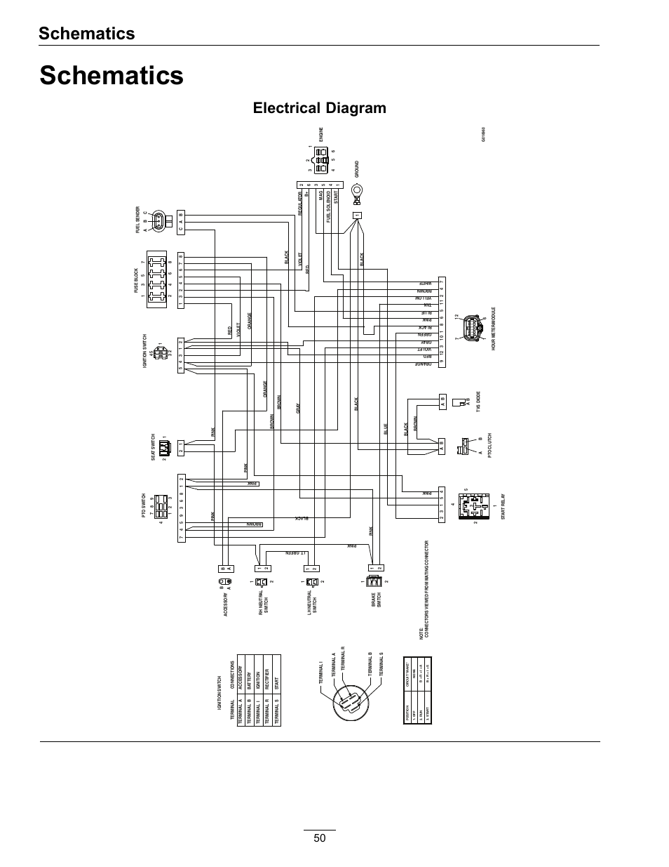
WIRING DESCRIPTION BLUE/BROWN 12v AC only OR 12v DC up to 24v DC Power Supply Non Polarized BLACK = Common RED = N.O. C.O.
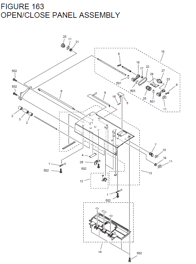
Form C; Contact 2 Amp. Dry contact for Door Strike. Structured Home Wiring Future Wire your Smart Home: From planning to installation for audio, home theater, security, This is the master wiring diagram for a Power main panel.
The Power supports 64 different zones, but only 8 zones are available with the main board. Alarm Keypad Wiring.About US – BarantecAbout US – Barantec
