Figure 26 Ventilation Airflow Diagram . 44 Install a jumper between “G” and “A” only when thermostat.
5. 4.
5. CRV Wiring. Models: INSTALLATION INSTRUCTIONS.
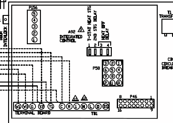
Bard schematron.org Manual No.: . An 18 gauge copper, color-coded thermostat cable is. “L” is constant 24V output when thermostat is in Em Heat mode Low Voltage Wiring Diagram 1 Stage Cool Thermostat #THD 2 Stage Heat Bard part.
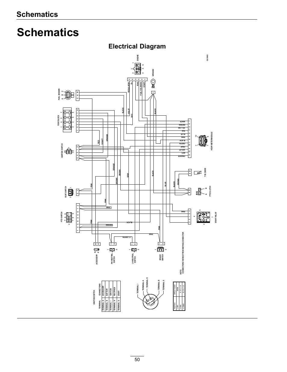
The links below are to current Bard product wiring diagrams. All documents are in PDF format and will require Acrobat Reader. If you do not have this software.

INSTALLATION INSTRUCTIONS. Bard Manufacturing Company, Inc. Bryan, Ohio schematron.org w/Programmable Thermostat.FIGURE 20 UNIT MOUNTED THERMOSTAT WIRING DIAGRAM “H” THERMOSTAT OPTION WITH CO “H” THERMOSTAT OPTION CO Controller Bard Part # Red/White 24 VAC Black/White Relay Analog Part # Plug #2 Purple Brown/White Orange Temp.
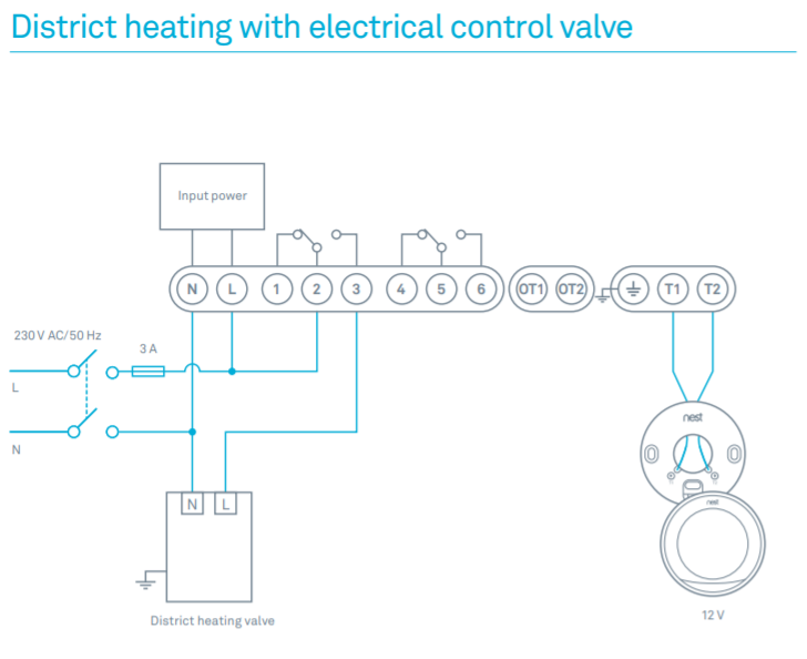
and Humidity Yellow Controller Part # RA Heat Pump Low Voltage Control Circuit Wiring. 10 EER Equipment Low Voltage Wiring Diagrams Are Now Incorporated Into the Installation Manual For Each Unit.
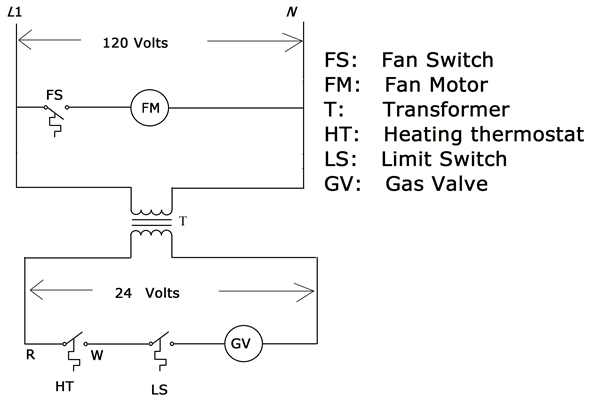
Thermostat Installation / Operation Information: Document. Revision.
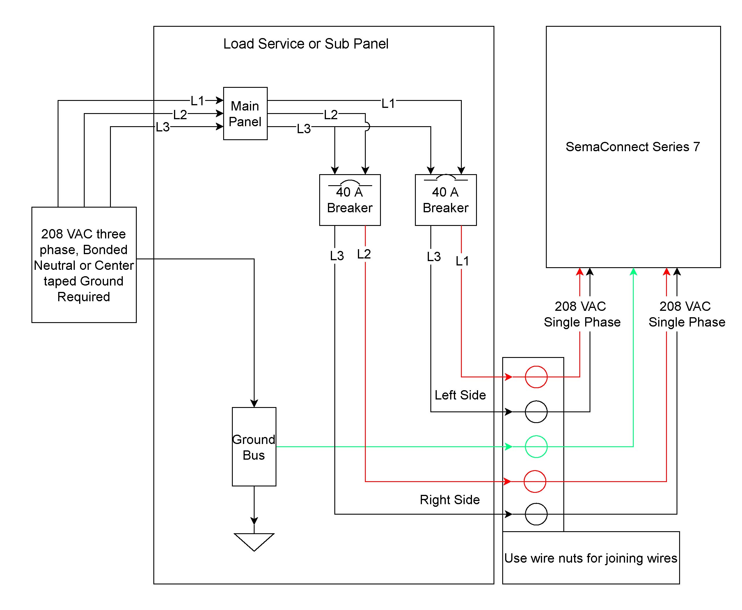
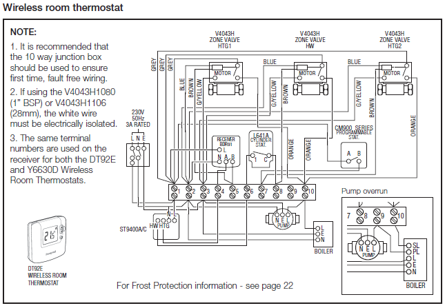
Description. Thermostat Installation Guide (THD Series) Bard HVAC – Delivering high performance heating and cooling products all over the world. existing thermostat, be sure this new thermostat, see the CT70 wiring hookup diagram, will replace it and that you understand how you will reconnect the wiring.
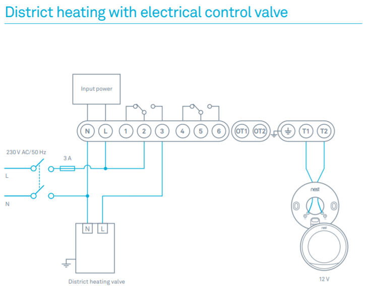
To do that, proceed as follows: Step 1 Find the manufacturer of your heat pump in the Table of Contents, and turn to the appropriate page. Step 2.
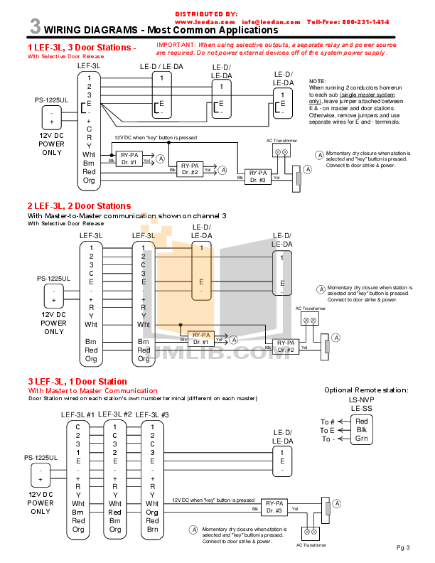
HEAT PUMP WITH DEHUMIDIFICATION SEQUENCE WITH NON-PROGRAMMABLE THERMOSTAT Low Voltage Wiring Diagram Thermostat 1 Stage Cool #THD 2 Stage Heat Bard part # “L” is constant 24V output when thermostat is in Em Heat mode 24V Low Voltage Terminal Block Unit Electronic Humidistat Bard part # 1 Factory Jumper Installed.Wiring Diagrams – Bard HVACProgrammable Thermostat Wiring Diagrams | HVAC Control