
A stop start circuit diagram, also known as a control circuit diagram, is a schematic representation of the electrical connections and components involved in a stop-start control system. This type of circuit is commonly used in industrial applications to control the operation of motors or other electrical devices.
The purpose of a stop start circuit is to provide a means of starting and stopping a motor or other equipment in a controlled manner. It allows for remote control of the equipment, ensuring that it can be safely operated from a distance. The circuit typically includes a start button, a stop button, and a set of contacts that control the power supply to the motor.
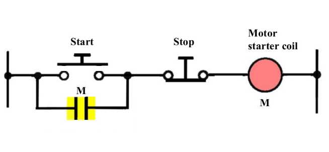
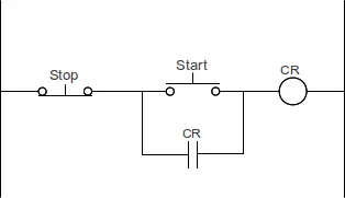
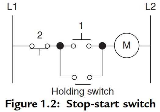
In a basic stop start circuit diagram, the start button is usually connected in series with a set of contacts that close when the button is pressed. This completes the circuit and allows current to flow to the motor. Once the motor is running, the start button can be released, and the contacts will remain closed, maintaining power to the motor.
The stop button is connected in parallel with the start button. When the stop button is pressed, it opens the circuit, breaking the flow of current to the motor and causing it to stop. The stop button is often designed to be a latching button, meaning it will stay in the open position until it is manually reset.
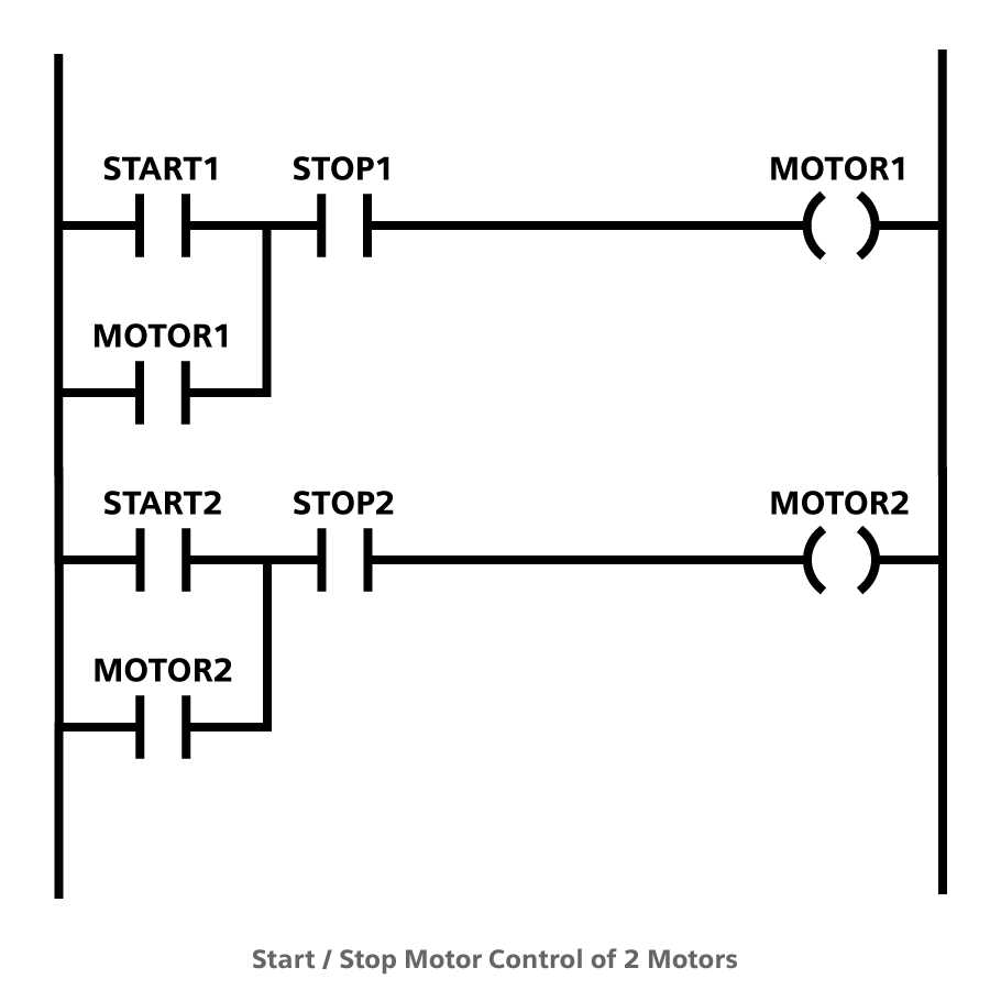
Basic Stop Start Circuit Diagram
A basic stop start circuit diagram is a schematic representation of how a motor control system operates. It shows the various components and connections that are involved in starting and stopping an electric motor.
The diagram typically includes the following components:
- Power supply: This is the source of electrical energy that powers the motor.
- Start button: This button is used to initiate the motor’s start sequence.
- Stop button: This button is used to stop the motor once it is running.
- Motor: The electric motor itself, which converts electrical energy into mechanical energy.
- Control relay: This is an electromagnetic switch that controls the flow of electrical current to the motor.
- Overload relay: This device protects the motor from excessive current by interrupting the circuit if an overload is detected.
- Contactor: This is a large switch that is controlled by the control relay and allows the motor to be connected or disconnected from the power supply.
In operation, the start button is pressed, which energizes the control relay and closes the contactor. This allows current to flow to the motor, which starts running. Once the motor is running, the stop button can be pressed to de-energize the control relay and open the contactor, stopping the motor.
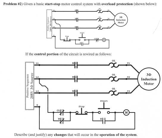
It is important to include overload protection in the circuit to prevent damage to the motor in case of an overload condition. The overload relay monitors the current flowing through the motor and interrupts the circuit if it exceeds a predetermined threshold.
A basic stop start circuit diagram is a fundamental representation of a motor control system and is used as a starting point for designing more complex control systems. Understanding this diagram is essential for troubleshooting and maintaining motor control circuits.
What is a Stop Start Circuit?
A stop start circuit, also known as a start-stop circuit or control circuit, is an electrical circuit that controls the operation of a motor or other electrical device. It is commonly used in industrial settings to control machines and equipment, as well as in automotive applications for starting and stopping engines.
The main purpose of a stop start circuit is to provide a safe and reliable means of starting and stopping a motor or device. It consists of various components, such as switches, relays, and control devices, which work together to control the flow of electricity and allow for smooth starting and stopping of the motor.
The basic operation of a stop start circuit involves a start button and a stop button. When the start button is pressed, it closes a switch that energizes the motor and starts it. The motor will continue to run until the stop button is pressed, which opens the switch and de-energizes the motor, causing it to stop.
In addition to the start and stop buttons, a stop start circuit may also include other control devices, such as overload relays, which protect the motor from damage in case of overheating or overload conditions. These devices monitor the current flowing through the motor and trip the circuit if the current exceeds a certain threshold.
Overall, a stop start circuit is an essential component in many electrical systems, providing a safe and reliable means of starting and stopping motors and other electrical devices.
Components of a Stop Start Circuit
A stop start circuit, also known as a control circuit or an on-off circuit, is commonly used in industrial applications to control the operation of machines or equipment. It allows an operator to start and stop the machinery as needed, providing a convenient and safe way to control the equipment.
The components of a stop start circuit typically include:
1. Start button
The start button is the primary control device used to initiate the operation of the machinery. When pressed, it sends a signal to the circuit, allowing the flow of electricity to energize the motor or equipment. The start button is usually colored green to indicate its purpose.
2. Stop button
The stop button is the control device used to interrupt the flow of electricity to the motor or equipment. When pressed, it sends a signal to the circuit to stop the operation of the machinery. The stop button is usually colored red to indicate its function, providing a visual indication to the operator that the equipment has been stopped.
3. Control relay
The control relay is an electromechanical device that acts as a switch in the circuit. It is activated by the start button and de-activated by the stop button. When the control relay is energized, it allows current to flow to the motor or equipment, starting its operation. When the control relay is de-activated, it interrupts the flow of current, stopping the operation of the machinery.
4. Overload relay
The overload relay is a protective device that protects the motor or equipment from excessive current. It is connected in series with the control relay and monitors the current flowing through the circuit. If the current exceeds a certain threshold, indicating an overload condition, the overload relay opens the circuit, stopping the operation of the machinery and preventing damage to the motor or equipment.
5. Control transformer
The control transformer is used to step down the voltage supply to a suitable level for the control circuit. It ensures that the control circuit operates at a safe and appropriate voltage level, preventing damage to the control components and improving the overall safety of the system.
6. Power supply
The power supply provides the electrical energy needed to operate the stop start circuit. It may be a direct current (DC) power supply or an alternating current (AC) power supply, depending on the requirements of the system.
Overall, the components of a stop start circuit work together to provide a reliable and efficient control system for industrial machinery. The start button initiates the operation, the control relay allows the flow of electricity, the stop button interrupts the operation, the overload relay protects the equipment, and the control transformer and power supply ensure the proper functioning of the circuit. Understanding these components is essential for designing, troubleshooting, and maintaining stop start circuits in industrial applications.
Wiring Diagram for a Stop Start Circuit
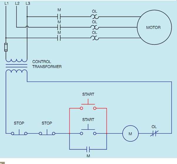
A stop start circuit is a basic electrical circuit used to control the operation of a motor. It allows for the starting and stopping of the motor using a push button switch or other types of control devices. The wiring diagram for a stop start circuit typically consists of several components, including a power supply, a control transformer, control relays, push button switches, and motor starters.
At the heart of the stop start circuit is a control transformer, which steps down the voltage from the power supply to a lower voltage suitable for the control relays and other control devices. The control transformer is connected in parallel with the power supply and provides the necessary power for the control circuit.
The control relays are responsible for controlling the operation of the motor. They are typically electromagnetic switches that are energized or de-energized based on the state of the push button switches. The control relays are connected in series with the motor starters and provide the necessary control signals to start or stop the motor.
The push button switches are used to manually start or stop the motor. They are typically momentary switches that are normally open or normally closed. When the start button is pressed, it closes the circuit and energizes the control relays, which in turn closes the motor starters and starts the motor. When the stop button is pressed, it opens the circuit and de-energizes the control relays, which in turn opens the motor starters and stops the motor.
In addition to the control transformer, control relays, and push button switches, the wiring diagram for a stop start circuit may also include other components such as overload relays, motor contactors, and auxiliary contacts. These components provide additional protection and control features for the motor.
In summary, a wiring diagram for a stop start circuit is a basic electrical diagram that shows the connections and components used to control the operation of a motor. It typically includes a power supply, control transformer, control relays, push button switches, motor starters, and other components. The wiring diagram allows for the manual starting and stopping of the motor using the push button switches and provides protection and control features for the motor.
How Does a Stop Start Circuit Work?
A stop start circuit, also known as a control circuit or a start-stop system, is a fundamental circuit used in electrical control systems to start and stop motors or other equipment. The purpose of the circuit is to provide a convenient and safe way to control the operation of machinery or equipment.
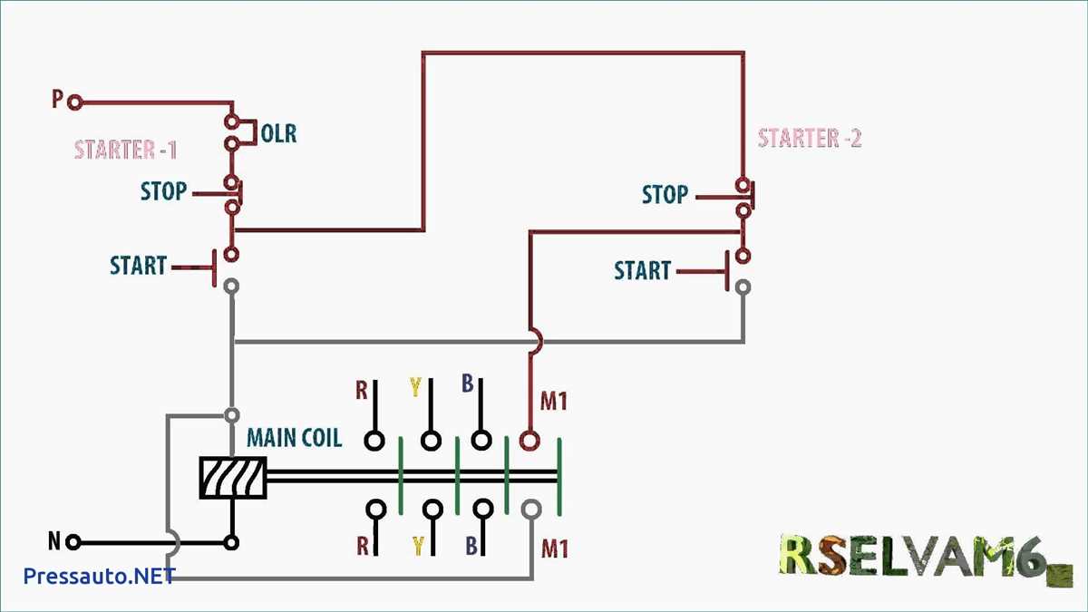
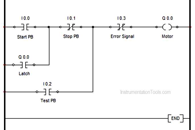
The basic stop start circuit diagram consists of three main components: a start button, a stop button, and a coil or contactor. When the start button is pressed, it energizes the coil, which in turn closes the contacts of the contactor and starts the motor or equipment. When the stop button is pressed, it de-energizes the coil, causing the contacts of the contactor to open and stop the motor or equipment. This simple but effective circuit allows for easy and reliable control of the machinery or equipment.
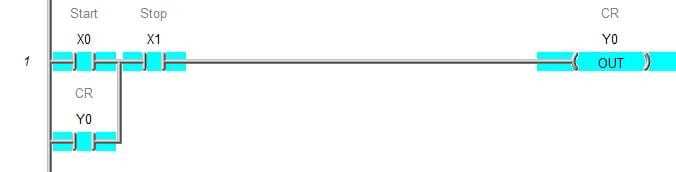
The stop start circuit is typically implemented using a ladder diagram, which is a schematic representation of the circuit using standard electrical symbols. In the ladder diagram, the start button and stop button are represented by normally open contacts, and the coil or contactor is represented by a coil symbol. The circuit can also include other components, such as overload relays or interlocks, to provide additional safety or protection for the motor or equipment.
Overall, the stop start circuit is a crucial component in many industrial and commercial applications, providing a safe and efficient way to control the start and stop of motors and equipment. Its simplicity and reliability make it a widely used circuit in various control systems.
Applications of Stop Start Circuit
The stop-start circuit is a fundamental circuit used in various electrical systems to control the operation of motors and machines. It is widely used in industries, automobiles, and appliances to ensure the efficient and safe functioning of equipment.
1. Industrial Applications:
In industrial settings, the stop-start circuit is commonly used in conveyor belt systems, pumps, and other machinery. This circuit enables the operators to start and stop the equipment as needed, preventing unnecessary wear and tear, and reducing energy consumption. It also provides a safety mechanism by allowing emergency stops in case of any malfunction or hazard.
2. Automotive Applications:
In automobiles, the stop-start circuit is an important feature in modern vehicles that helps to save fuel and reduce emissions. It automatically shuts down the engine when the vehicle is stationary for a certain period of time, such as at traffic lights or during traffic congestion, and restarts it when the driver releases the brake or accelerates. This feature significantly improves fuel efficiency and reduces carbon dioxide emissions, contributing to a greener environment.
3. Appliance Applications:
The stop-start circuit is also utilized in various household appliances, such as refrigerators, air conditioners, and washing machines. It allows for the automatic start and stop of these appliances based on user requirements or predefined settings. For example, a refrigerator’s compressor will start when the temperature rises above a certain threshold and stop when the desired temperature is reached. This functionality not only ensures optimal performance but also saves energy and extends the lifespan of the appliances.
4. Energy Saving Applications:
Additionally, the stop-start circuit can be implemented in energy-saving systems such as lighting control. It allows for the automatic on/off switching of lights based on occupancy or time schedules. This not only eliminates the need for manual operation but also reduces energy wastage by ensuring that lights are only used when necessary.
In conclusion, the stop-start circuit has a wide range of applications in various industries and everyday devices. It plays a crucial role in improving energy efficiency, enhancing equipment performance, and providing safety features. Its versatility and usability make it an essential component in many electrical systems.
Benefits of Using a Stop Start Circuit
The stop start circuit is a simple yet effective control circuit used in various electrical systems. It offers several benefits, making it a popular choice in many applications.
- Energy Efficiency: One of the major advantages of using a stop start circuit is its ability to save energy. By automatically stopping the operation of equipment when it is not in use and starting it again when needed, the circuit ensures that power is not wasted unnecessarily. This can result in significant energy savings, reducing both costs and environmental impact.
- Extended Equipment Lifespan: Another benefit of the stop start circuit is that it helps to prolong the lifespan of the equipment it controls. By preventing continuous operation, the circuit allows the equipment to rest and prevents excessive wear and tear. This can reduce maintenance and replacement costs in the long run.
- Improved Safety: The stop start circuit also enhances the safety of the system. By automatically stopping the equipment during emergencies or when certain conditions are met, it helps prevent accidents and damage. It ensures that the equipment is only operated when it is safe to do so, reducing the risk of injuries or property damage.
- Convenience and Control: With a stop start circuit, operators have more control over the equipment. They can easily start or stop the equipment as needed, eliminating the need for manual intervention. This simplifies the operation process and makes it more convenient for the operators.
- Cost Savings: Overall, the use of a stop start circuit can result in significant cost savings. By reducing energy consumption, extending equipment lifespan, and improving safety, businesses can save money on electricity bills, maintenance, and repairs. These cost savings can contribute to improved profitability and efficiency.
In conclusion, the stop start circuit offers numerous benefits in terms of energy efficiency, equipment lifespan, safety, convenience, and cost savings. Its simple design and effectiveness make it a valuable addition to various electrical systems.
Q&A:
What is a stop start circuit?
A stop start circuit is a circuit that controls the stopping and starting of a motor or other electrical device.
What are the benefits of using a stop start circuit?
The benefits of using a stop start circuit include improved safety, energy savings, extended equipment life, and increased efficiency.
How does a stop start circuit improve safety?
A stop start circuit improves safety by allowing for controlled starting and stopping of equipment, reducing the risk of accidents and injuries.
How does a stop start circuit save energy?
A stop start circuit saves energy by automatically turning off equipment when it is not needed, preventing unnecessary power consumption.
How does a stop start circuit extend equipment life?
A stop start circuit extends equipment life by reducing wear and tear caused by continuous operation, allowing for periods of rest and maintenance.