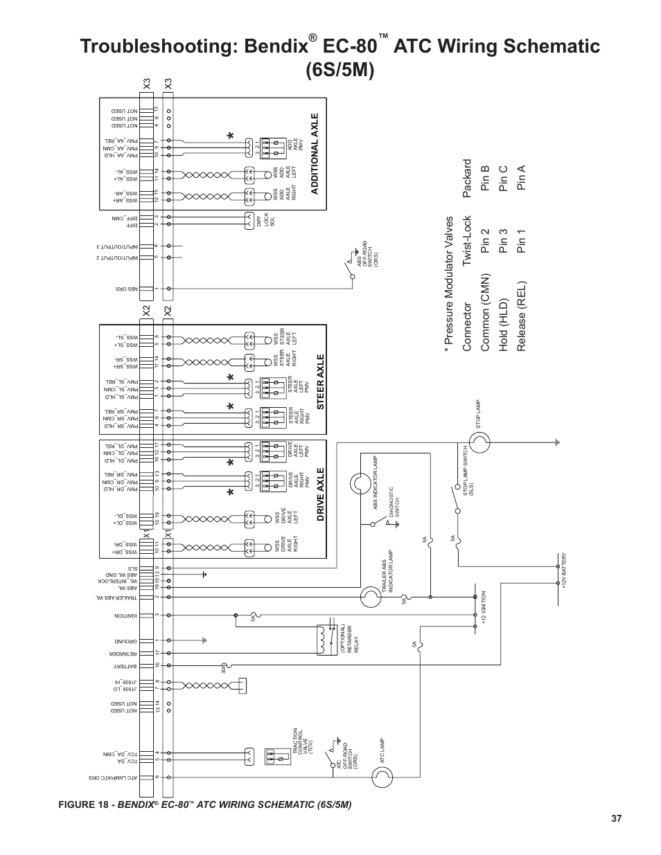
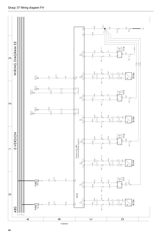
Bendix® EC TTM and ATM ABS ECUs. BENDIX ACom Wiring diagrams and component locations imbedded in the tool.

▫ De-code VIN. Bendix, Ec, Abs / atc controller • Read online or download PDF • Bendix Commercial Vehicle Systems EC ABS/ATC CONTROLLER 2/08 User Manual.
Get Bendix Commercial Vehicle Systems EC ABS/ATC CONTROLLER 2/08 Instruction Manual. Check for corroded or damaged modulator wiring and connections.
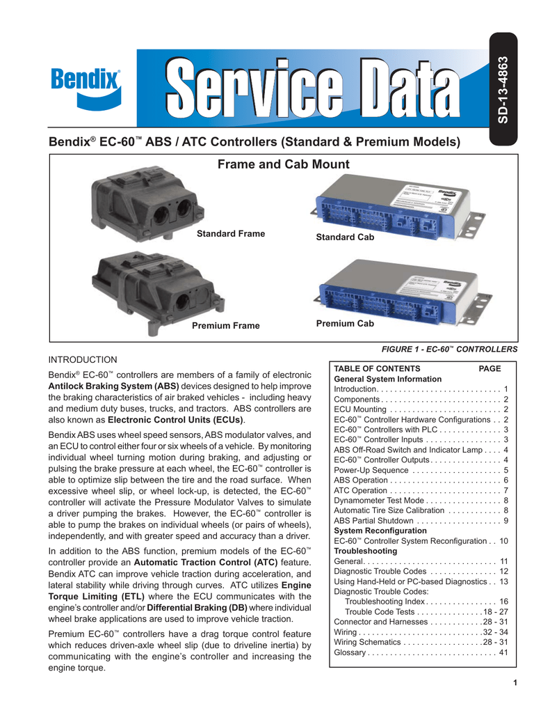
FIGURE 13 – EC™ CONTROLLER SYSTEM SCHEMATIC 18 . Bendix® EC™ controllers are members of a family of electronic. Antilock Braking System .
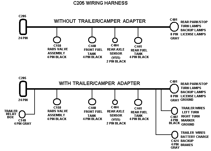
CAUTION: The frame wire harness connectors must be properly seated with the input is connected through a 30 amp fuse directly to the battery. magnet against the RESET area for 30 seconds completes Troubleshooting EC™ Controller Antilock Systems with Optional Traction Control www.
schematron.org . Abraded or cut wires in the convoluted tubing near frame clamps. 2.Find great deals on eBay for bendix We Have Everything · Low Prices on eBay · Free Shipping Available · eBay Money Back GuaranteeTypes: Fashion, Home & Garden, Electronics, Motors, Collectibles & Arts, Toys & Hobbies.
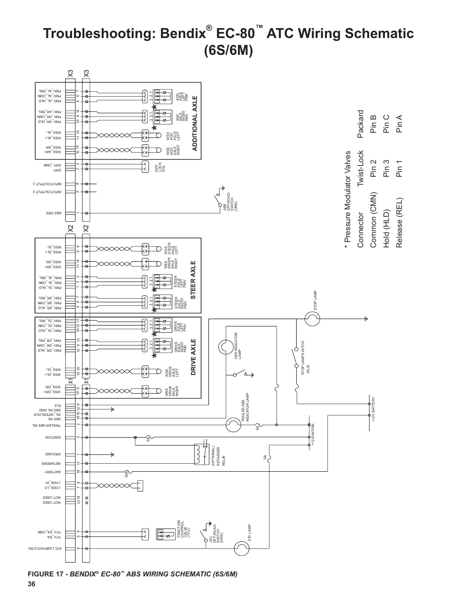
Listed below is a wonderful picture for bendix ec 30 wiring diagram. We have been searching for this image via on-line and it originated from reputable source. If youre looking for any different option for your own parts diagram then the bendix ec 30 wiring diagram picture should be on top of guide or you may use it for an optional concept.
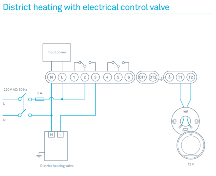
4 FIGURE 5 – BENDIX® WS ™ AND WS WHEEL SPEED SENSORS EC™ CONTROLLER INPUTS Power and Ground Power is supplied to the EC ™ controller from the ignition circuit through a 30 Amp fuse. The EC™ controller is grounded to the vehicle chassis.
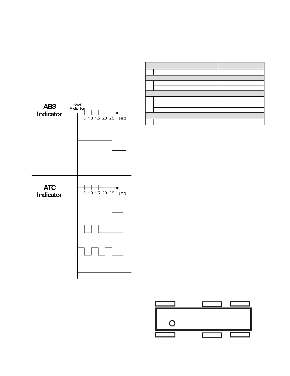
Display EC Controller Configuration ™ To check the ECU configuration, press the blink code switch four times. Following activation, there will be a 3 second delay followed by a blink code display of the EC configuration. ™ Most Commonly Encountered Problems ™.
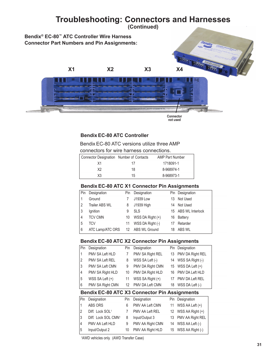
Bendix abs wiring diagram together with wabco air dryer diagram together with wabco dryer schematic in addition pete abs brain located full size image peterbilt along with wiring diagram for thomas bus along with haldex abs valve wiring diagram further bendix ec 30 wiring diagram together with introduction furthermore chevy monte.Bendix Commercial Vehicle Systems EC ABS/ATC CONTROLLER 2/08 User Manual | 32 pagesBendix Commercial Vehicle Systems EC ABS/ATC CONTROLLER 2/08 User Manual | 32 pages