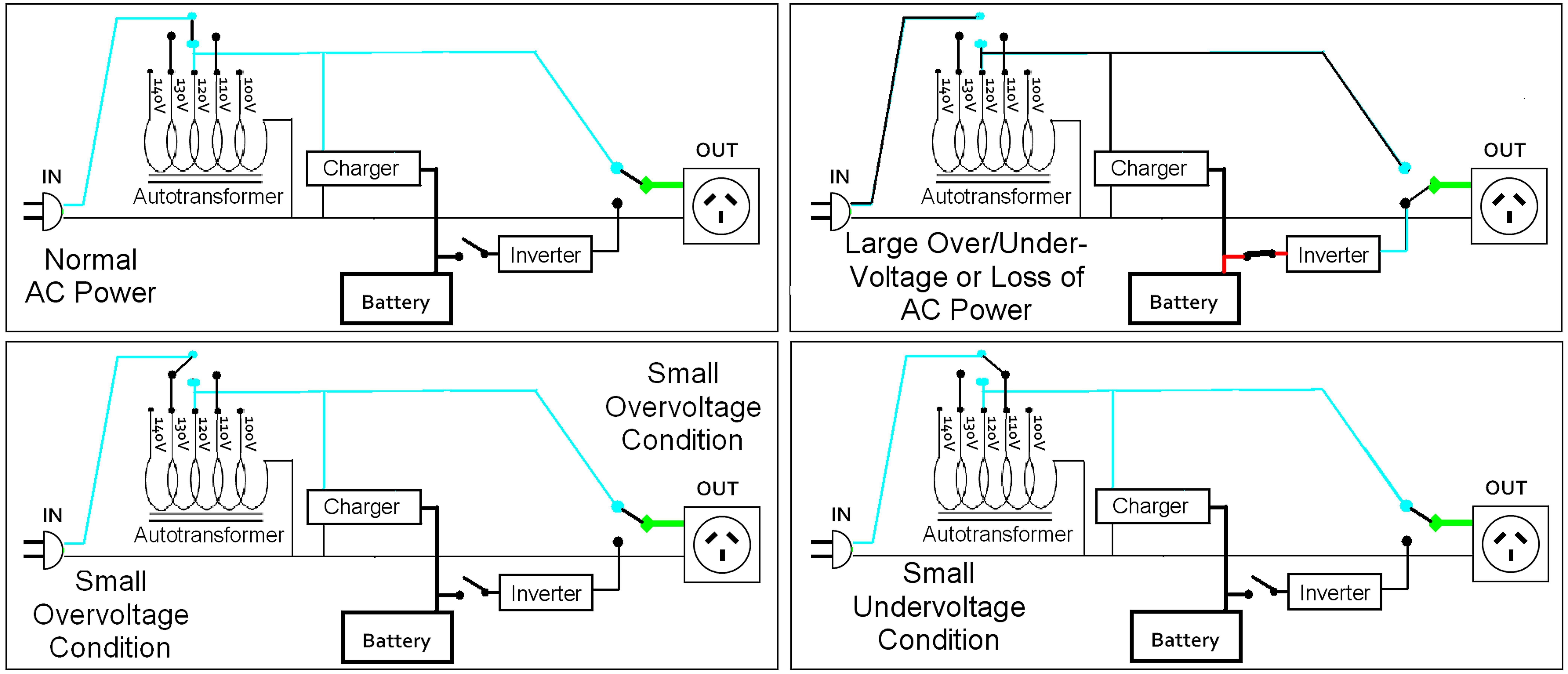
Beuler BUM Waterproof 12 VDC Automotive 5-Pin Relay – Connection diagram The Beuler BUM relay is unique being that it is a waterproof 12 volt. There are a few questions in there, so I will try to address them all.
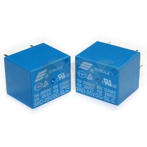
The Bueler Time Delay relays are unlike the vast majority of other relays you. Relay Wiring Diagram. A relay is typically used to control a component that draws high amperage.
The relay allows full power to the component without needing. Buy the Beuler 12 volt relay without mounting tab, Negative spike Beuler W 12 VDC Automotive 5-Pin Relay – Pin diagram Description; Specs; Product Reviews; Questions and Answers; Installation Videos & Manuals.
Install thermostat into the head or intake manifold. Route the black wire from the relay to the thermostat and cut it to length. Crimp one of the red female spade.Relay Wiring Diagram.

A relay is typically used to control a component that draws high amperage. The relay allows full power to the component without needing a switch that can carry the amps. The switch only controls the relay.
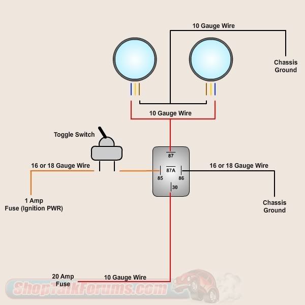
The relay then provides a direct connection to the battery. Find great deals on eBay for beuler relay.
Shop with confidence. The Beuler BUTD is a very cool relay. Have you ever wanted to have something stay on for some time after a momentary button is pressed?
The BUTD relay is just the relay for you. This relay is a time delay relay with adjustable timings allowing you to control any device/5(24).
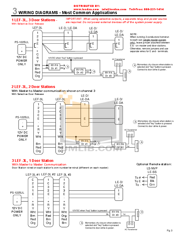
I do want the fan to run, but for only a couple of minutes after I switch the car off, so I installed a Beuler Time Delay relay. However, it fails to function as designed when I .
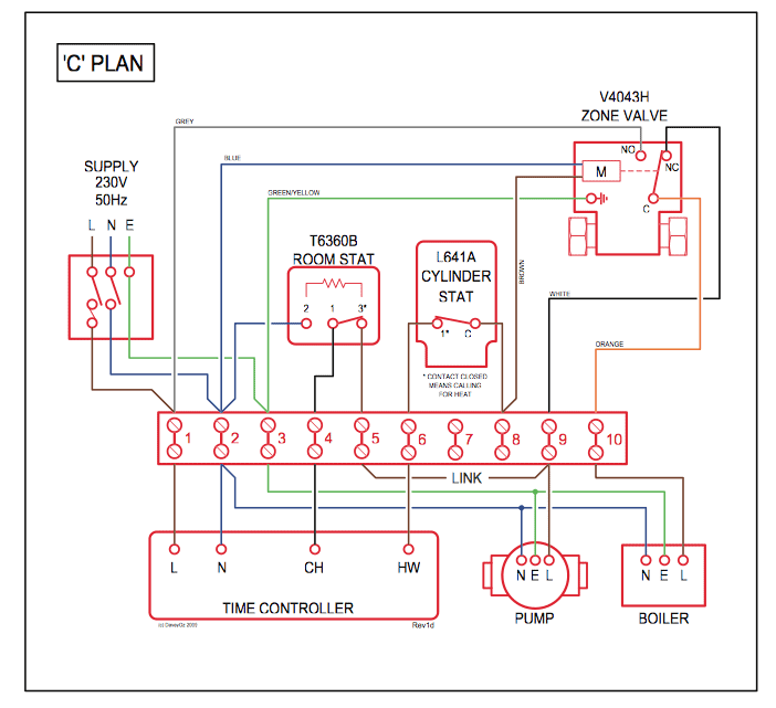
The square relay pinout shows how the relay socket is configured for wiring. This pinout image is only a 2-pole diagram for room on the page purposes, but you can get the picture here with this one since a 3-pole will just have 1 more set of contacts.electrical – Time Delay Relay and Flyback Diode – Motor Vehicle Maintenance & Repair Stack ExchangeHow To Wire A Relay
Basic Automotive Relay Operation and Simple Wiring