Introducing the Titan BrakeRite RF the first Electric over hydraulic brake control.
manual override is transmitted by radio frequency to the control module. control pressure as sent from the in-cab electronic brake controller (sold towed vehicle brake performance from the driver’s position plus allowing manual.
or overheat and may also cause the BrakeRite EHB unit to overheat. (The actual performance from the driver’s position plus allowing manual override.
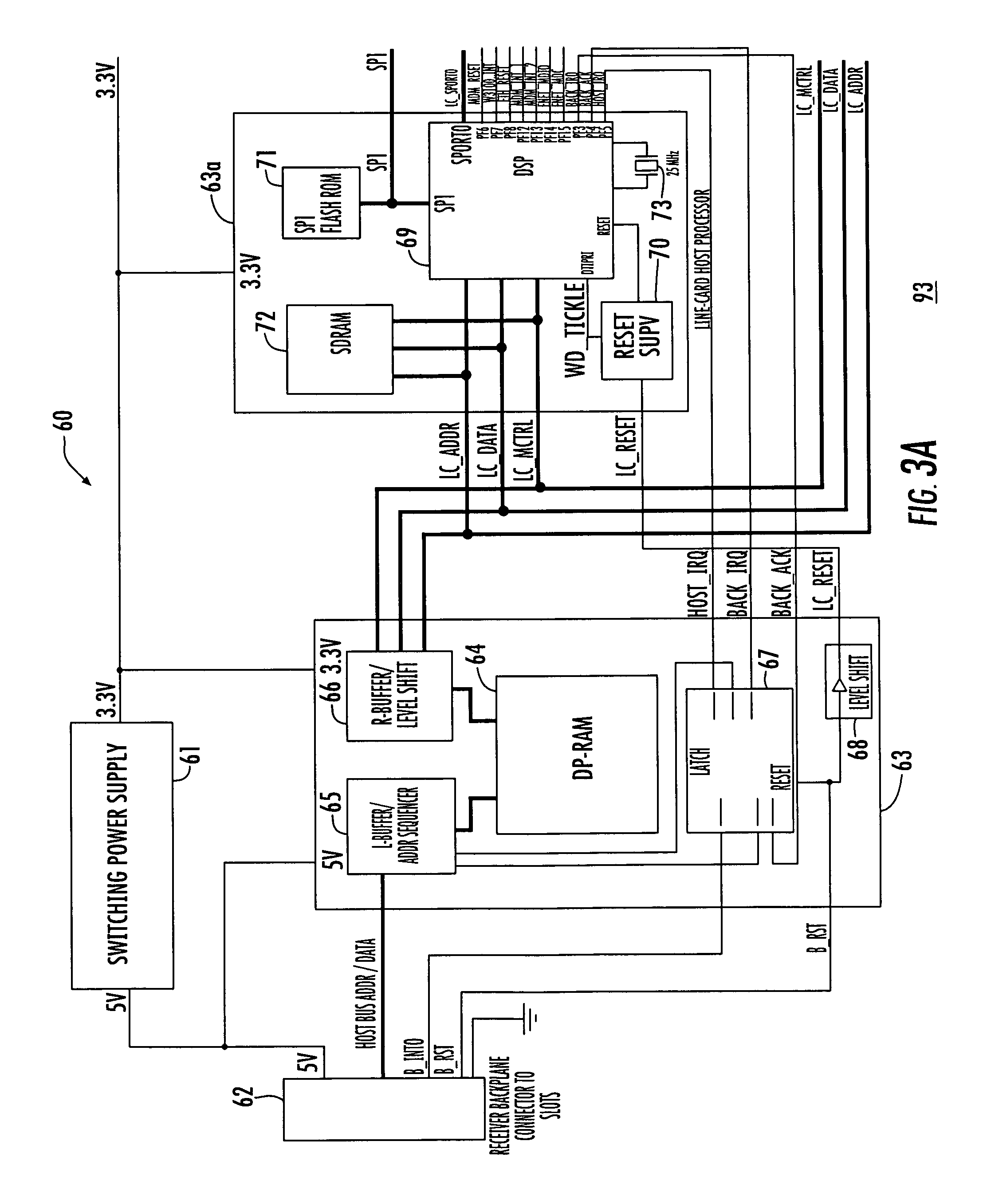
Titan BrakeRite. Electric Over Hydraulic Note: The in-cab control unit supplied with this brake . SD Control Module Mounting Instructions. towed vehicle brakes this is achieved by applying the manual over-ride on the “in -cab” brake controller, or in a breakaway situation the towed vehicle brake.Wire the Actuator on RV Trailer 1.
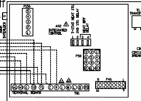
White 12 Ga. to neutral – Attached to negative side of battery. No frame grounds.
2. Black 12 Ga.
to 12v power – Preferred: This should go into the junction box and attach to the other power wires. automotive wire and the control leads 4 mm. Undersized electrical wiring will result in line losses and directly effect the function of the BrakeRite EHB.
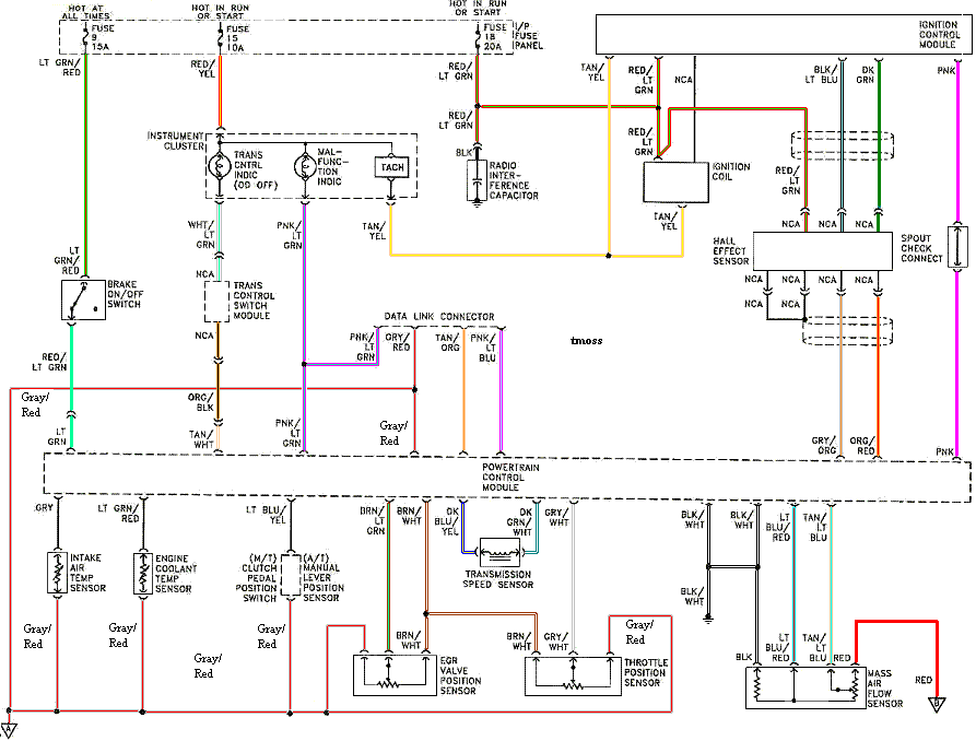
We recommend the TITAN Trailer Brakes Power Kit is used, ask your Dealer or call TITAN Trailer Brakes direct on 07 – The BrakeRite EHB includes a Surge Protection circuit that is. The BrakeRite EHB & BrakeRite II “SD” Towed Vehicle Brake Actuation requires an external control module to perform its intended function.

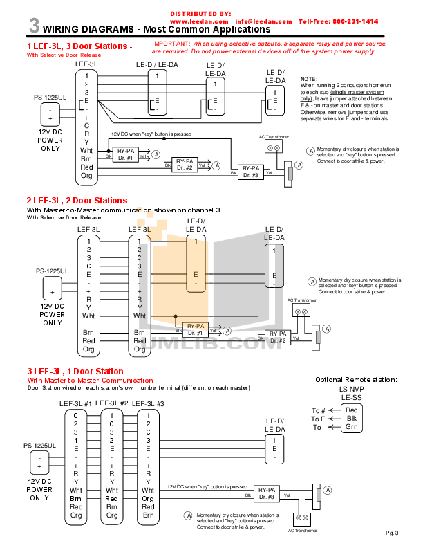
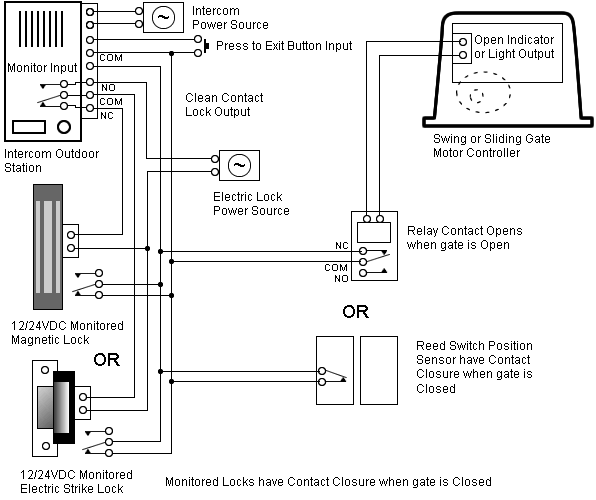
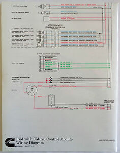
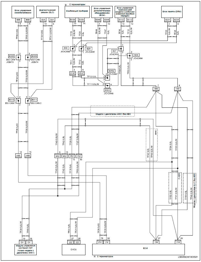
the various connections (consult the wiring diagram, BrakeRite EHB on page 19). This unit is operated from most standard “in-cab” electric brake controllers (provided output signal is a PWM. The features of the BrakeRite II – Severe Duty include: Utilizes the standard proven EHB electronic control board, potted and enclosed in a remote mounted control module.
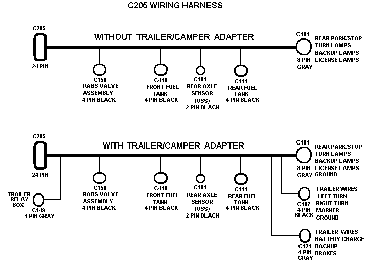
Provides complete plug-in wiring harnesses to simplify field installation. In the event of . 1 BrakeRite II 2 RF Control Module 3 RF Wiring Harness 4 RF In-Cab Controller 5 BrakeRite II Breakaway Battery Harness 6 BrakeRite II Breakaway Battery Switch BRAKERITE II SD Kit (includes everything listed above) BRAKERITE II RF Kit (includes everything listed above) BRAKERITE II SD Parts List.Troubleshooting Titan BrakeRite SD Electric-Hydraulic Actuator Kit | schematron.orgElectric over Hydraulic Brake Module – Suggestions – Boat Talk – Chaparral Boats Owners Club
