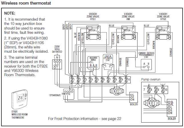
Installation Handbook, AutroSafe Interactive Fire Detection System, P- ASAFE-INSTALL/DGB Rev.
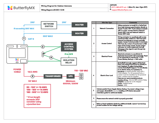
J, , AL_Com+ Connection on Communication Module BSL Connector J5 .. The protection shown in the schematic of port equivalent above is made for 1kV High Energy Surge.
BSL 01/05/ Ni – Cd. CLASS 2 OUTPUT.
UNIVERSAL INPUT Select the appropriate wiring diagram to connect the emergency driver to the AC driver. EM/BSL Emergency LED driver (maximum nominal lumens module output in EM Brown-out, short circuit and voltage surge protection. • Overcharge ..
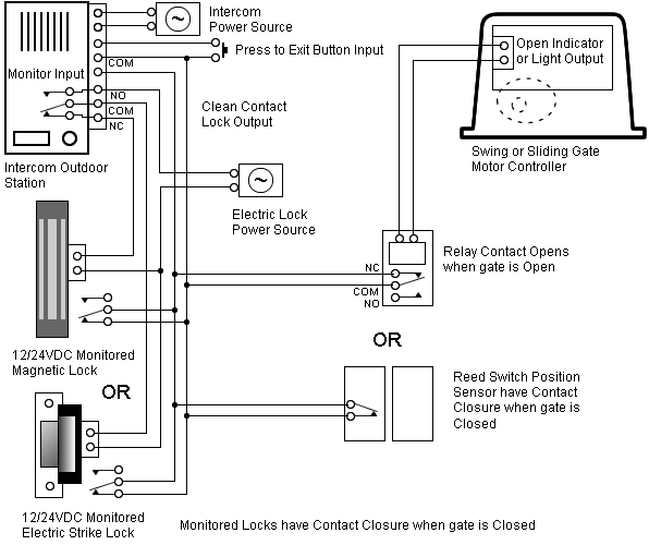
LMIO Connection and Wiring Diagram. Class 2 wiring. BSL 01/05/ Ni – Cd. CLASS 2 OUTPUT.
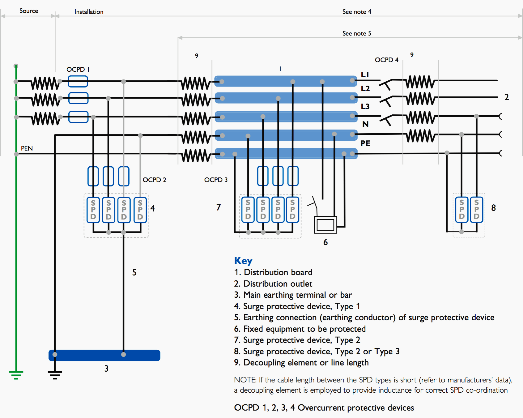
UNIVERSAL INPUT Select the appropriate wiring diagram to connect the emergency driver to the AC driver. The MidNite Solar Surge Protector Device (MNSPD) is a Type 1 device, designed for Please read the following installation manual carefully and follow.Wiring Diagrams for Surge Arresters Wiring of 1 and of 3 x DEHNguard and 1 x DEHNgap C/T. Installation of Class 1 and Class 2 for 3-phase.
Class 1 and Class 2 protection for VAC. Installation of Class 1 and Class 2 Single Phase. Installation of Class 1 and Class 2 for 3-Phase.
top. The Site Wiring Fault (SWF) LED light is only present on V UPS and Surge products. On APC UPS products this indicator is typically on the rear panel.
The purpose of this indicator light is to warn you that there are problems with your building wiring that may result in a shock hazard. Installation of Surge Protection Device.
From Electrical Installation Guide. Jump to: navigation, search.
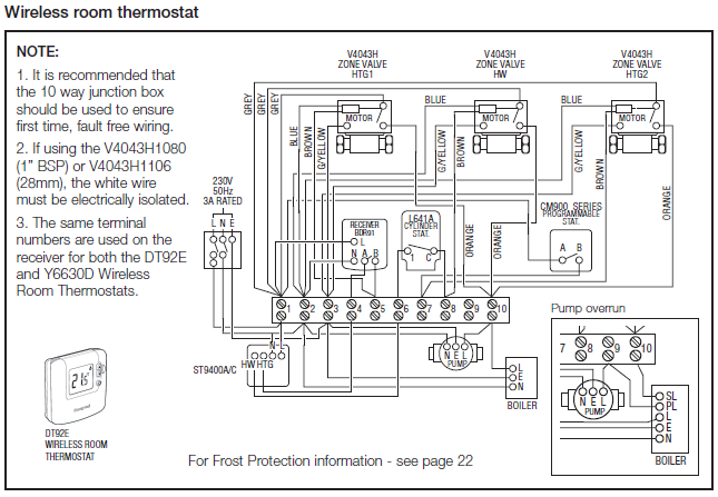
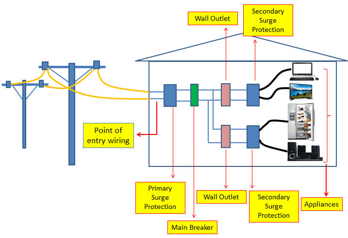
General rules of electrical installation design: Connection to the MV utility distribution network: Connection to the LV utility distribution network. The surge protector allows the coordinated use in an EMC-oriented Lightning Protection Zones Concept in accordance with IEC The protective effect is adapted to the EMC interference immunity (conducted high energy interference impulses) for fieldbus measuring, control, and equipment.
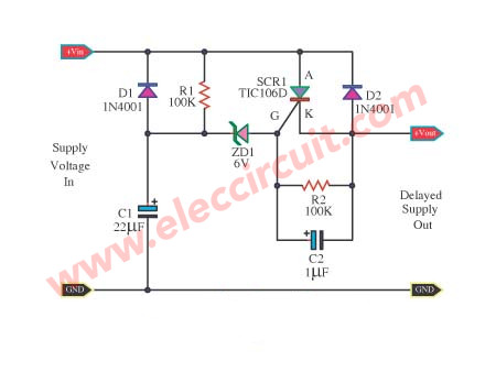
STEP #3 WIRING THE EMERGENCY DRIVER > Select the appropriate wiring diagram to connect the emergency driver to the AC driver and LED load. Make sure all connections are in accordance with the National Electrical Code and any local regulations.SURGE PROTECTION CIRCUIT PRINCIPLE and DESIGN – ElectronicsBelieversurge protector with switches | eBay
