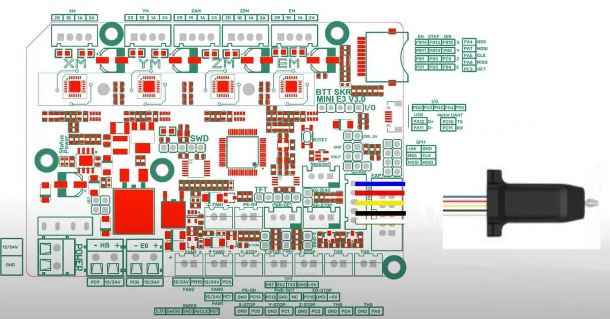
To ensure proper wiring and avoid hardware issues, follow the precise mapping of each terminal on the E3 V3 mainboard used in Ender 3 Pro models. Power inputs, stepper motor outputs, and sensor connections have designated slots that must be identified carefully to guarantee correct operation.
Heatbed terminals are located near the power supply section, typically marked with “HEATER” labels. Confirm polarity and connection points before energizing to prevent shorts. The hotend heating element requires connection to the dedicated output, clearly separated from other heating components.
Stepper motor plugs for X, Y, Z axes, and extruder are arranged in a row, each with specific pin assignments for coil wiring. Double-check cable orientation to avoid stepper misbehavior or skipped steps. Fan headers and thermistor inputs are positioned nearby for efficient thermal management and temperature monitoring.
Pinout Reference for the E3 V3 Board in RepRap Setup
Use the official wiring layout to correctly attach motor drivers, endstops, thermistors, and display units. The X, Y, and Z stepper motor outputs are clearly labeled, with separate pins for direction and enable signals. Ensure the heated bed and hotend heaters are connected to the designated MOSFET terminals for optimal power delivery.
Endstop inputs are split into minimum and maximum limit switches, with standard 3-pin connectors supporting signal, ground, and voltage. Thermistor ports are marked with analog input labels; connect sensors directly without resistors to maintain accurate temperature readings.
The LCD interface supports standard 20×4 or 12864 displays via dedicated ports; pay attention to the ribbon cable orientation to avoid damage. Power inputs require stable 12V or 24V supply lines, with a separate connector for USB communication.
For motor driver modules, use the onboard pin headers with the proper jumper settings to switch between UART and standalone modes. Cooling fan outputs have PWM control pins for silent operation adjustments. Follow the exact pin allocation to prevent short circuits and ensure smooth firmware integration.
Pinout and Wiring for Stepper Motor Interfaces on E3 V3 Board
To ensure proper operation of stepper motors, connect the motor cables according to the exact pin assignments on the E3 V3 control board. Incorrect wiring may cause motor failure or erratic behavior.
- Step Pins: Each axis step signal is assigned to a dedicated pin. Connect the step wire from the driver to the step output of the board to enable precise movement commands.
- Direction Pins: Direction signals control motor rotation orientation. Match the motor’s direction wire to the corresponding board pin to ensure correct motor turning.
- Enable Pins: These pins activate or disable the motor driver. Connect the enable wire so that the board can manage motor power states.
- Motor Phases: Stepper motors typically have two coils (A and B). Connect the A+ and A-, B+ and B- wires from the motor to the dedicated output terminals on the control board. Verify coil polarity to avoid motor jitter.
Follow these detailed wiring notes:
- Use the 4-pin header for each axis labeled with
STEP,DIR,ENABLE, andGND. - Connect the motor’s coil wires to the matching pairs on the board:
A+toA+,A-toA-, and the same for B. - Ensure cable shielding is grounded to reduce electrical noise affecting signal integrity.
- Verify the power supply provides stable voltage matching driver requirements before finalizing wiring.
- Test each motor individually after wiring to confirm correct rotation and response to control signals.
Connection Details for Endstops and Thermistors on SKR E3 V3 Board
Endstops require connection to designated signal pins labeled typically as X-, Y-, and Z-endstop inputs. Use mechanical switches or optical sensors compatible with 3.3V or 5V logic levels. Connect signal wires to the designated input pins, GND to the common ground, and VCC only if the sensor requires external power. Avoid mixing 5V and 3.3V devices on the same input to prevent damage.
Thermistors must be wired to the dedicated thermistor inputs marked on the board, usually labeled T0, T1, etc. Connect the two leads of the thermistor to these terminals ensuring stable contact and proper polarity if specified. Use 100k NTC thermistors compatible with the firmware configuration to guarantee accurate temperature readings.
Ensure all connectors are firmly seated and pins correctly aligned to prevent intermittent signals. Use shielded cables or twisted pairs for long runs to reduce electrical noise affecting sensor readings. Verify pinout references in the board’s schematic to avoid cross-connection that can lead to sensor malfunction or board damage.
When replacing or upgrading sensors, cross-check pin assignments with updated documentation for this specific controller variant. Confirm firmware settings match the hardware wiring for proper endstop triggering and thermistor temperature monitoring.
Power Supply and Display Interface Wiring on the Board
For a stable power supply to the board, ensure that the 24V or 12V input is properly connected to the main power terminals. The voltage regulator circuit should be carefully set up to supply the required current to the system. Double-check the polarity to avoid short circuits or damage to the board.
The display module interface requires a separate connection, typically involving a 5V or 3.3V supply for the screen. This connection is usually made through a dedicated set of pins for easy identification. Ensure that the display’s data lines are correctly wired to the designated input/output ports. The connection for the screen’s backlight may require additional voltage regulation depending on the type of display used.
For proper communication between the microcontroller and the display, make sure that the data transmission pins are securely connected, ensuring a stable signal flow. Use the proper connectors or solder directly to the pins for a more reliable setup. Verify that any necessary pull-up or pull-down resistors are correctly placed to maintain signal integrity.