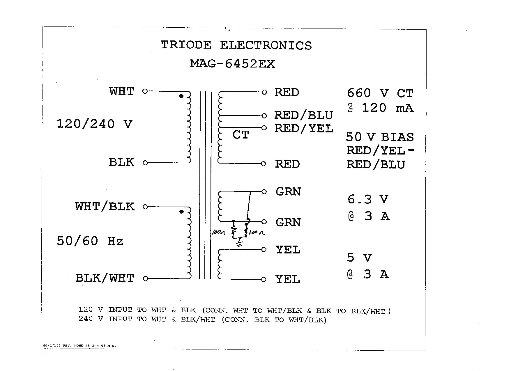
Wiring Diagrams.
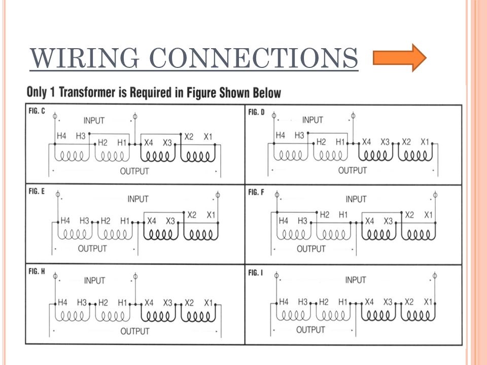
Buck-boost transformers are small single phase transformers designed to . Boosting V to V or V and vice versa for commer-. Steps for Selecting the Proper Buck-Boost Transformer .
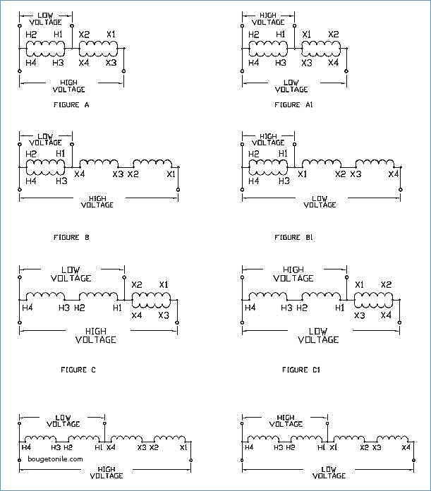
Units Rated x V Input: 24 x 48 V Output. CONNECTION.
INPUT. OUTPUT.
How to wire a Buck Booster Part 2
DIAGRAM. K IN COMIN. POWER.
How do I select the proper Buck & Boost Transformer to go from 208V to 240V, or from 240V to 208V?
(SUPPLY. WIRES.
/ t. I.
G. I.

/1. I ugh or box lied wtth the .
T Max. Size of.
How do I select the proper Buck & Boost Transformer to go from 208V to 230V, or from 230V to 208V?
Fuse or Breaker. 6. 6.
6. 6. FOR BUCK-BOOST TRANSFORMERS. DESCRIPTION rExobmple: volts Single phose available (Column 2- o ~o’umn you’ve been working with ond the wiring diagram. 1$ referenced.
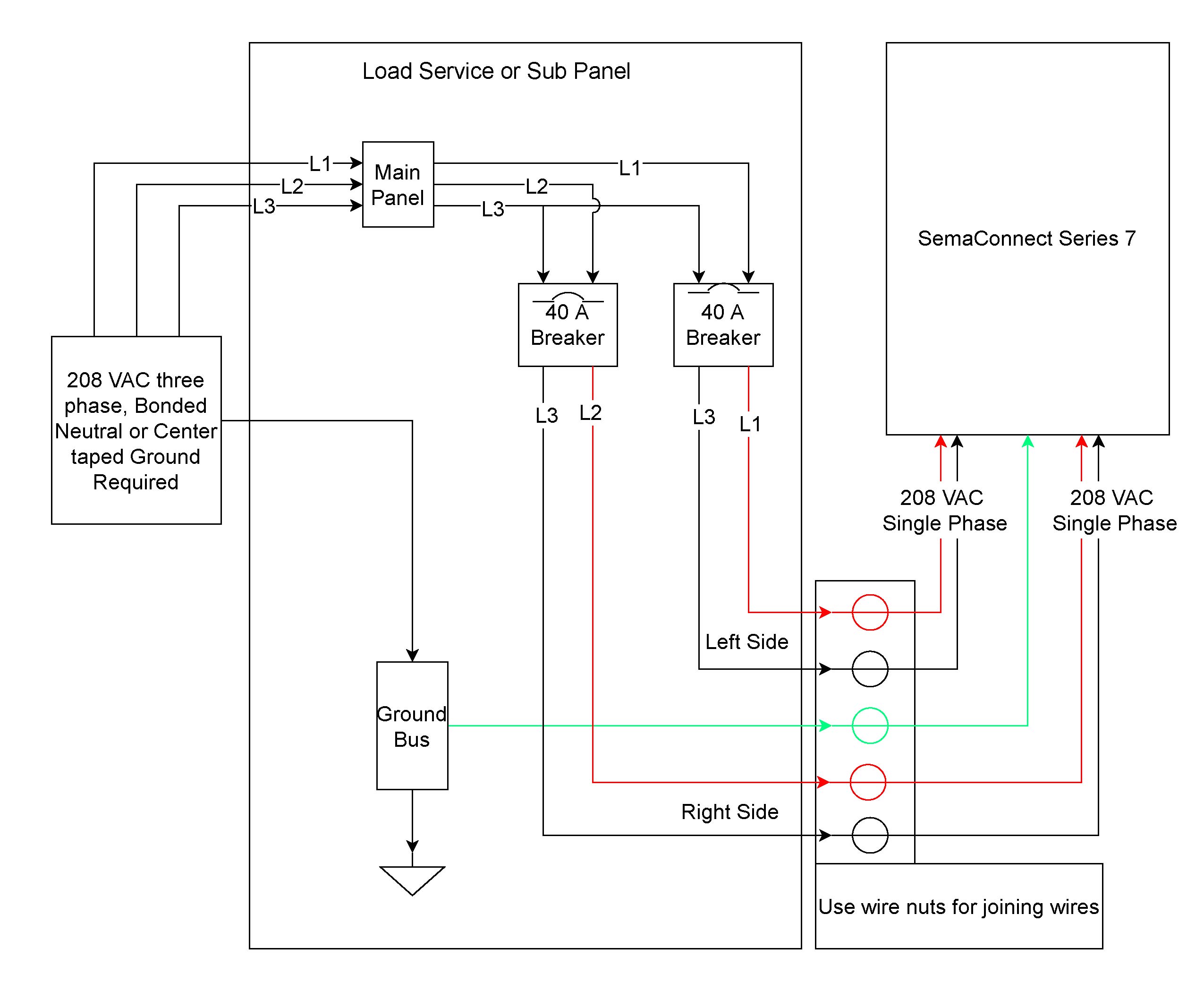
3 Phase Buck Boost Transformer Connection Diagram Square D Wiring
Table Volts Output, 60 Hertz. Steps for Selecting the Proper Buck-Boost Transformer . Units Rated x V Input: 24 x 48 V Output. CONNECTION.
INPUT. OUTPUT.
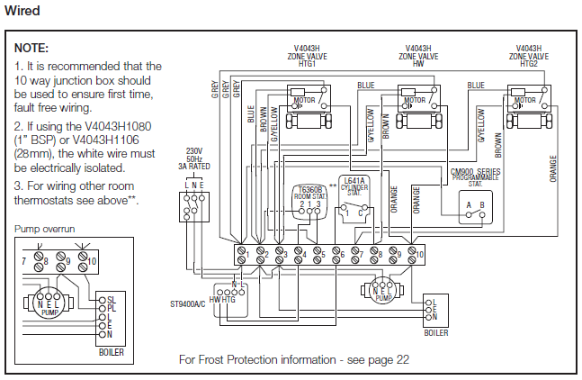
DIAGRAM. K IN COMIN.
POWER. (SUPPLY. WIRES.
/ t. I.
Buck Boost Transformer 208 to 240 Wiring Diagram Sample
G. I.
/1. I ugh or box lied wtth the .
T Max. Size of. Fuse or Breaker. 6. 6.
6. 6.
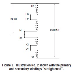
How do I select the proper Buck & Boost Transformer to go from V to V, or from V to C. Connect using wiring diagram #4 in Buck & Boost literature.buck-boost transformer: A buck-boost transformer is classified as an autotransformer. A buck-boost transformer provides a means of raising (boosting) or lowering (bucking) a supply line voltage by a small amount (usually no more than 20 percent).

A buck-boost is a transformer with two primary windings (H1-H2 and H3-H4) and two secondary. Buck-boost transformers are small, single phase, dry type distribution transformers designed and shipped as insulating/isolating transformers. They have a dual voltage primary and a dual voltage secondary.
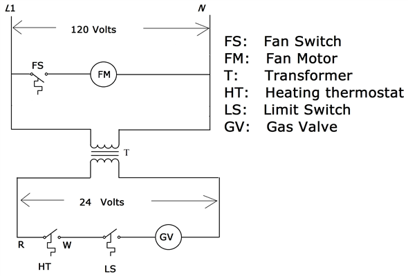
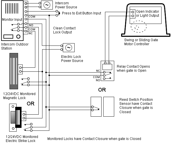
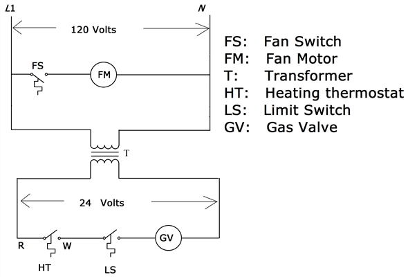
These transformers can be connected for a wide range of voltage combinations. buck boost transformer to wiring diagram – A Novice s Overview to Circuit Diagrams. An initial appearance at a circuit layout could be complex, but if you can .
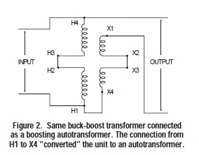
Buck – Boost Transformer Terms & Definitions Buck-Boost transformers are single phase, four winding transformers designed for two purposes. The first purpose is as a low voltage isolation trans-former for use on 12, 16, 24, 32, or 48 volt circuits.
When used as low voltage transformers, Buck-Boost transformers have capacities of kVA to Buck-Boost application Buck-boost transformers offer an economical solution to the adjustment of line voltages that are slightly above or below normal. When a buck-boost transformer is connected as an autotransformer, only a portion of the load kVA is actually transformed.
The majority of the load kVA is passed directly through to the source.Neutral required on the LINE side of 3 buck-Boost transformers from How do I select the proper Buck & Boost Transformer to go from V to V, or from V to V?