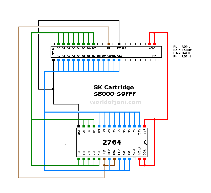
Here are some schematic diagrams of the Commodore Commodore 64 schematic diagram from the Service Manual VIA pinout.
On circuit diagrams, plugs are displayed as viewed from the back side, the solder side. Chips are Two solderable 6-pin male DIN plugs (Commodore serial plugs ).
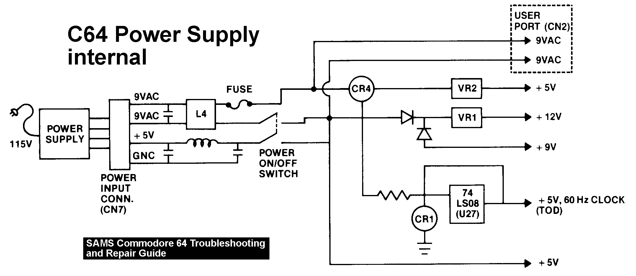
A shielded 5-wire or unshielded 6-wire cable of, preferably, at most 2 meters. It would be nice to find a standard diagram of the C64 power supply pinout, but there seems to be a 50/50 take on it. This is Both tables say pin 4 is either not connected, or 5+.
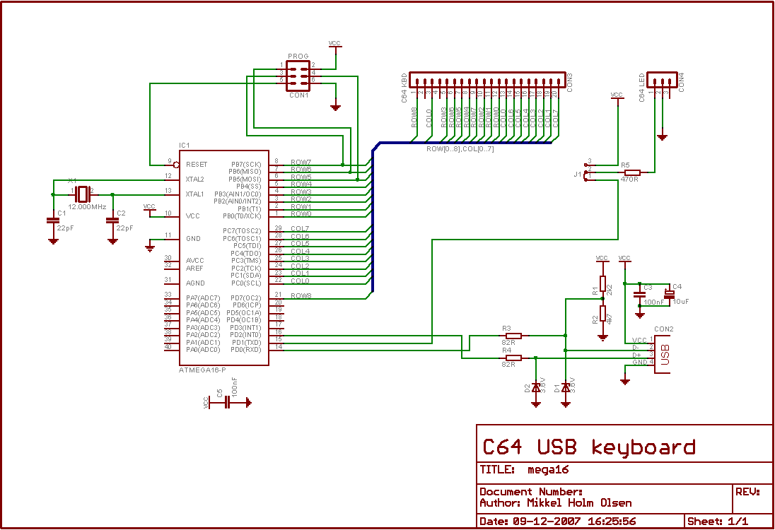
. Eh..
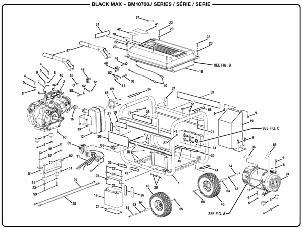
that schematic probably contains a typo. A port is a line, a wire, that the CPU can control.
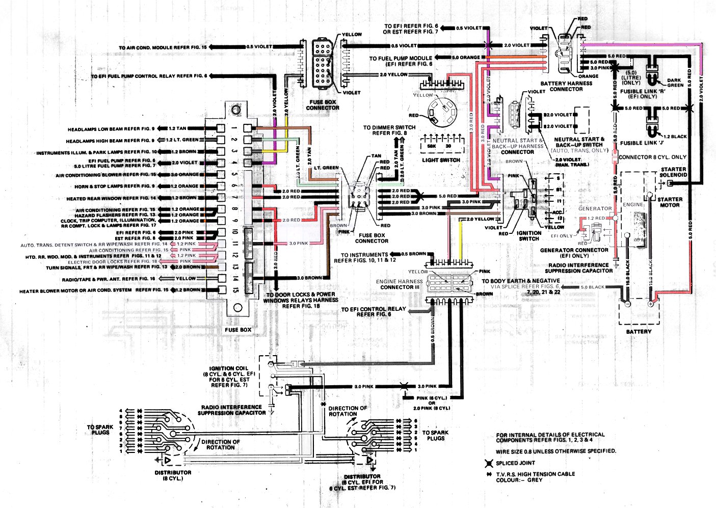
And indeed, when you look at the pinout diagram of the CIA above, reading down the left. Pin, Name.
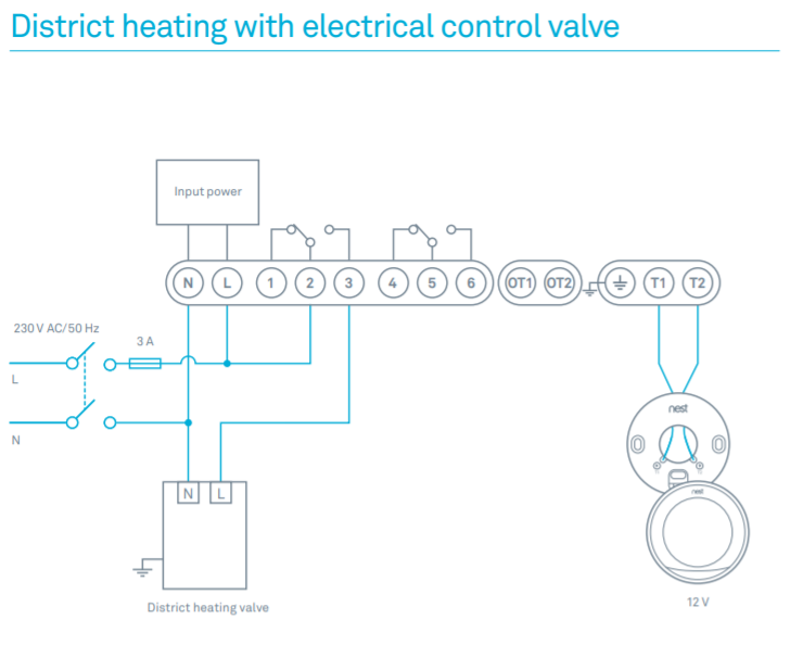
1, GND. 2, GND (5V negative pole).
3, GND. 4, nc or +5V in. 5, +5V in.
6, 9VAC in. 7, 9VAC in.
References. Commodore Manual.Pinout of C64 Control port and layout of 9 pin D-SUB male connector and 9 pin D-SUB female connector Pinouts / Devices / Connectors connector or cable wiring scheme6/10(6).
Oct 20, · Wow, is this true? You have found the Commodore Schematic Diagram?
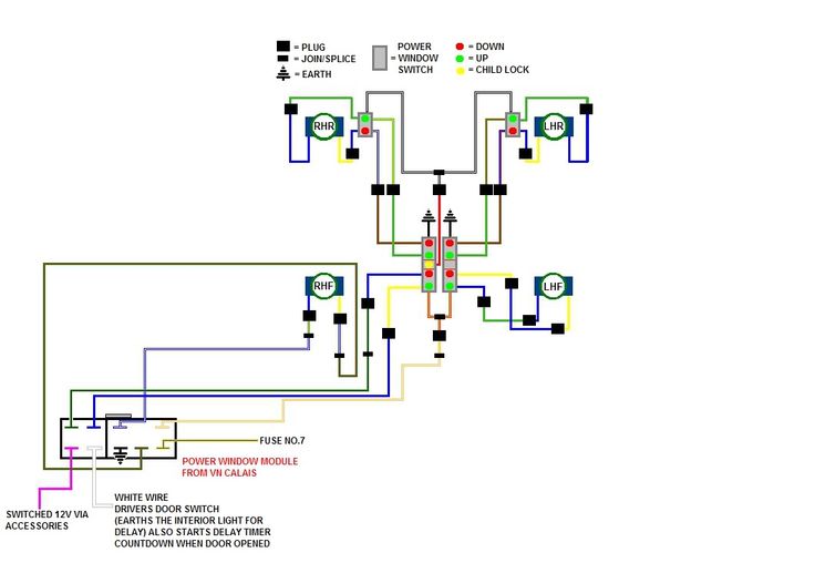
This has been rumoured to exist for years, this is the Holy Grail of the C64 world, if you do truly have one amigaman07! I will PM you with my offer! Seriously now, this sounds like the one that came with the “Programmers Reference Guide”.
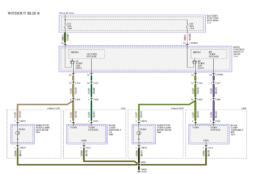
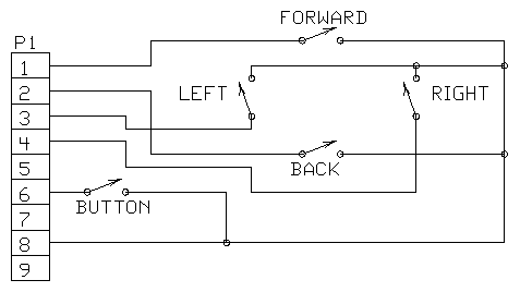
@Mabo: On the s-video pin to C64 pin diagram above (look for “Connections:”), I show pin #3 of the s-video connector (Luminance + Sync) is connected to pin #1 of the C64 (Luminance), regardless if you have the 5-pin or 8-pin connector on the C Older versions of C64 have 5 pin connector, newer versions of C64C have 8 pin connector.4/5(5). The joystick industry had de-facto wiring for wires used in joystick cables.
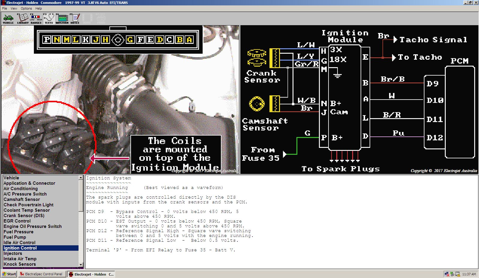
Here is the de-facto wiring used in Commodore 64 (many other manufacturers used same coloring): Pin Color Function 1 White Up 2 Blue Down 3 Green Left 4 Brown Right 5 no contact 6 Orange Fire button 7 Red +5V, max. 50 mA 8 Black Ground 9 no contact.C64 OS — An OS with Modern ConceptsC64 Control port pinout and wiring @ schematron.org
