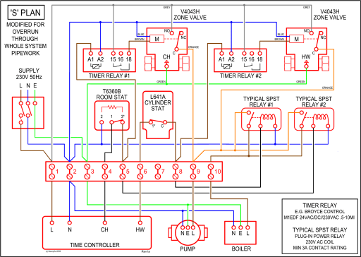
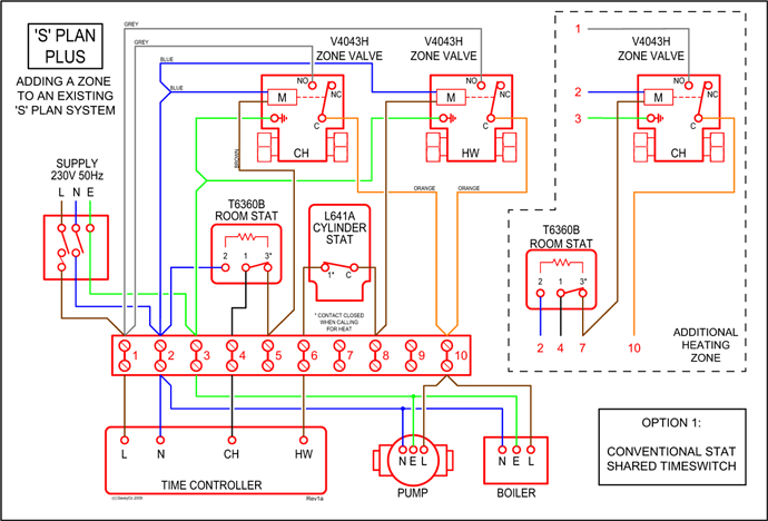
EEV two-pole valves for superheat control. general connection diagram is a practical example for preparing the unit wiring diagram that fully.
Fast and simple installation with all the parameters needed to start the unit password: control, compressor protection, defrost, alarms. WIRING DIAGRAMS .
accordance with all appropriate manuals and wiring diagrams, and started up by a qualified Carel USA . Connect Control Wiring: Wire the control cabinets.

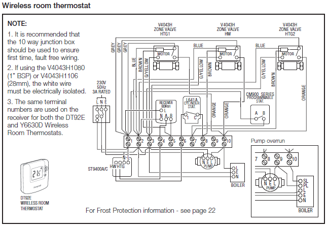
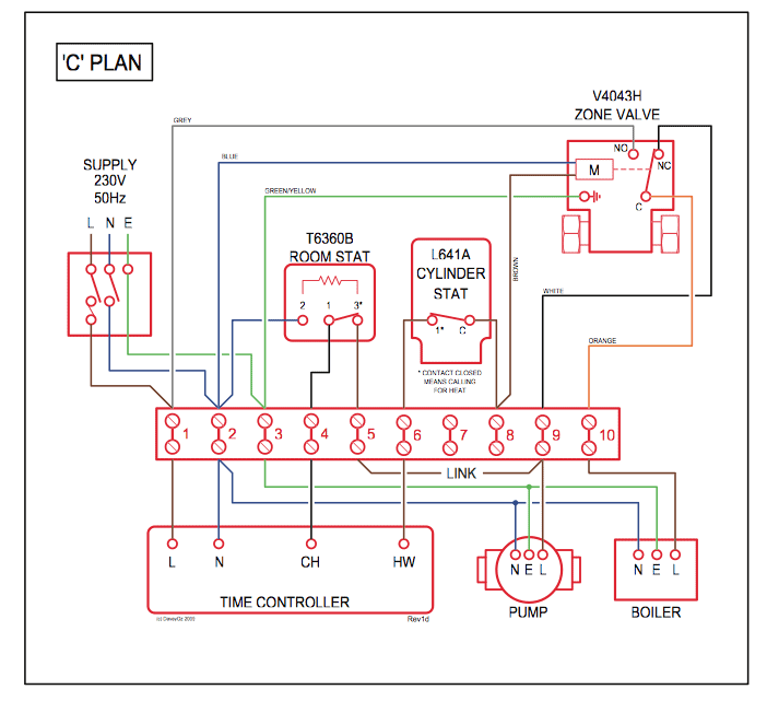
CAREL CONTROLLER Electrical Wiring Diagram Be sure all power sources are turned off before checking the electric wiring or appliances to. Carel Thermostat Wiring Diagrams. Standard Installation.
Installation with SSC ( Smart Speed Control). Installation for Spillover Fan.
1 2 4 5 7 8. Carel Digital.Carel easy User Manual.
With defrost control. Display the controller to make it operative. CAREL then recommends to check that the display does not show any alarm signals (see par.
“ Table of alarms and signals” on page 31), then set the time and date (in the models fi tted with RTC, see par. “ Clock and time band parameters. Carel Industries S.p.A.
announced that the acquisition of the entire share capital of Recuperator SpA, an Italian company active in the design, production and consumption of “air-to-air” heat. General characteristics ir33 represents the basic selection offered by CAREL for applications in refrigeration. A complete set of controls, from the single-relay version for static refrigerated units with normal temperature, with control only on the compressor, to the 4-relay version for ventilated, low temperature units, with compressor control, resistor or hot gas defrost, evaporation fans.
OEM CAREL code + – rel. 02/02/11 10 2.
INSTALLATION: DIMENSIONS, WEIGHTS, HOSE CONNECTIONS Positioning • To favour steam distribution, position the appliance so as to minimise the length of the steam outlet pipe (max 4 m). Wiring diagram IR33S7HR0E Confi gurations ir33 SMART is loaded with 4 default confi gurations (sets of parameters).
Each confi guration identifi es a specifi c refrigeration application, and can be identifi ed simply by the index (bn*) when switching the instrument .Adding an electronic refrigerator thermostat – Ocean Navigator – January/February CAREL EASY USER MANUAL Pdf Download.