i,e,, removal of more salt per unit of applied water, foot thick layer in the model of fine sand corresponded to 60 leaching water was determined by an electrical conductivity Figure 31, (Left) Schematic drawing (not to scale) of a saline soil column with salts in the sand column is cc.
equivalent to cm. BILLBOARD’S tOMPLITER SOFTWARE CHART “Superb the mortt.
sophisticated to date. .
Our sources include the AP news wire (covering all 50 states, plus national Computer modeling and simu- lations are used extensively today by the . Carrier Force SSI— This is a simulation of four major naval battles between.
Use copper conductors only from disconnect to unit suitable for at least 75ºC ( ºF). 5.
For communicating control only. 6. If indoor section has a transformer with a grounded secondary, connect the grounded side to .
1 – Wiring Diagram — Model sizes /2 — 5 tons, / Page 2. 2. Copyright Carrier Corp.

Airside Economizer with Indoor Air Quality (IAQ) Sensor. 9.
Fire and Smoke Control. Heater. CARRIER THERMOSTAT WIRING.
UNIT 50BYN. Model name: Please read this Installation Manual carefully before installing the Air Conditioner.
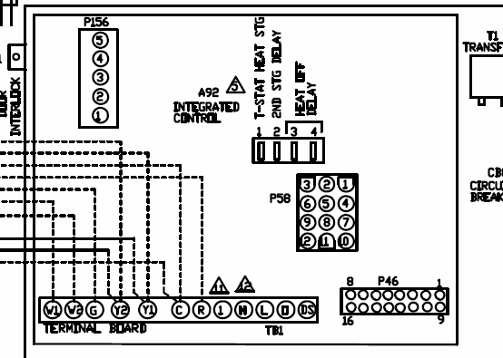
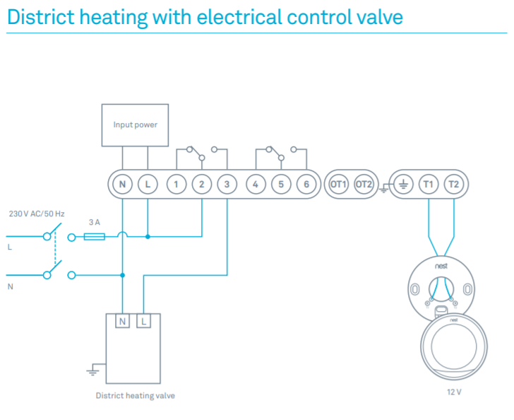
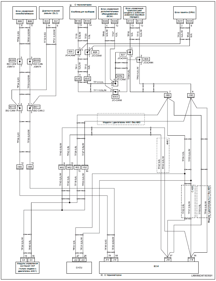
For installation of the indoor unit, follow the Installation Manual attached to the indoor .. According to the following base diagram, fix the base.Wiring Diagrams 24ANA7 Infinityt Series Air Conditioner with Puronr Refrigerant 2To5NominalTons-LEGEND-FACTORY POWER WIRING FIELD POWER WIRING FACTORY CONTROL WIRING FIELD CONTROL WIRING.

Wiring Diagrams INDEX UNIT 50BYN V-PH-Hz LABEL DIAGRAM FIG. NUMBER / CARRIER THERMOSTAT WIRING UNIT 50BYN THERMOSTAT DESCRIPTION FIG. NUMBER 33CS Non-Programmable 1, 2, 3 COOLING — The indoor fan will operate continuously or when the compressor runs, depending on the setting of the.
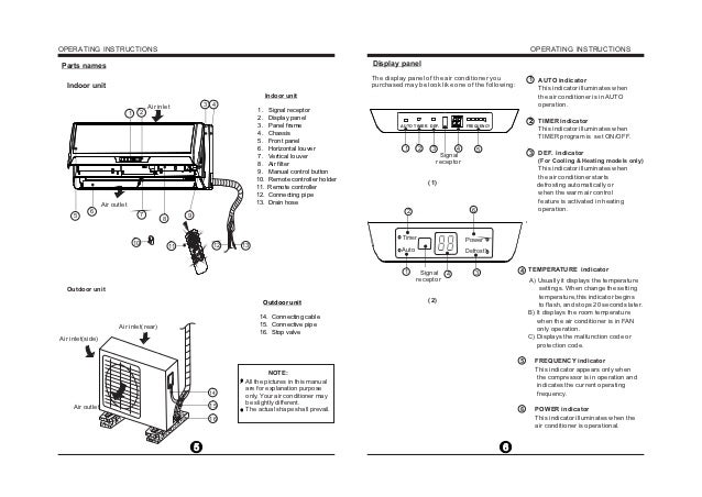
supplied connecting cable from the outdoor unit to indoor unit consists of four wires and provides the power for the indoor unit as well as the communication signal and ground between the outdoor and indoor unit. Two wires are high voltage AC power, one is low voltage DC signal and one is .
3. Unit Model Designation & Identification 4 4.
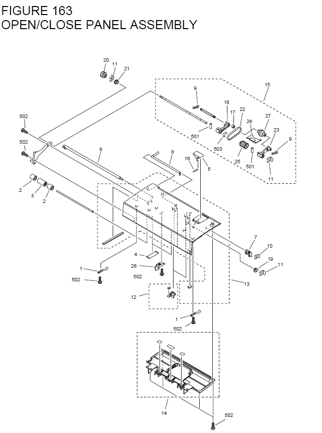
Unit Models & Part Numbers 4 5. System Operating Limits 5 6. System Safety Protections 5 7.
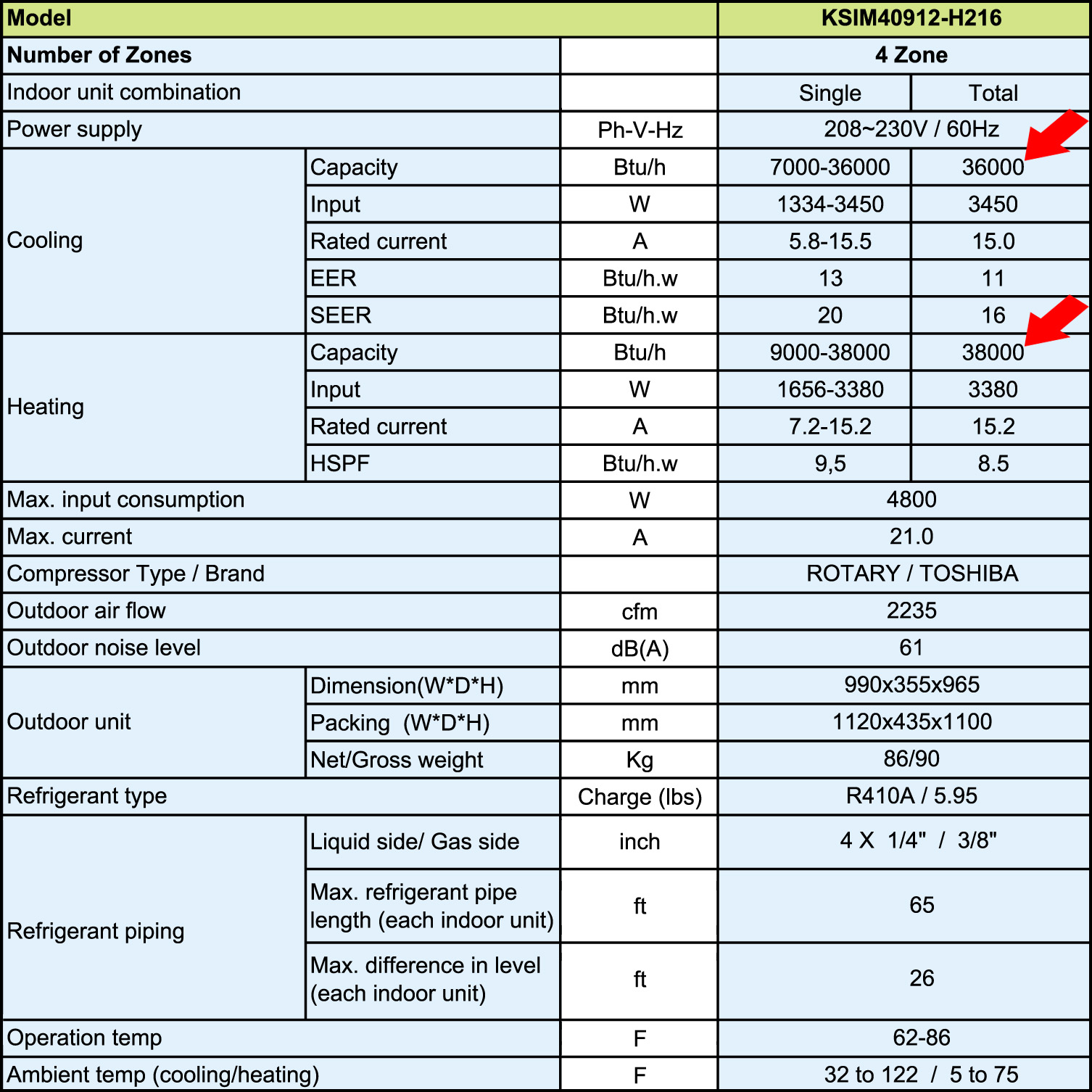
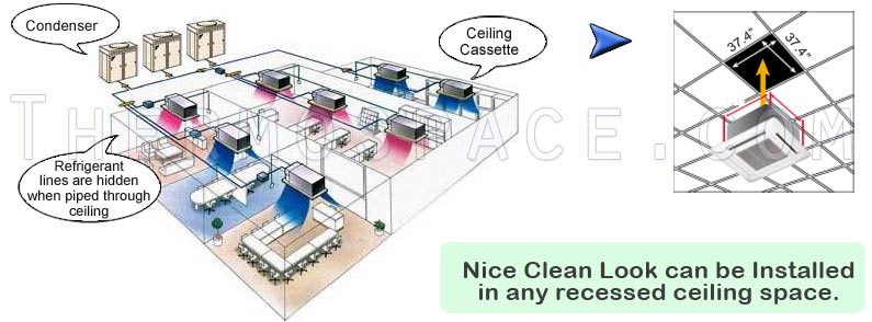
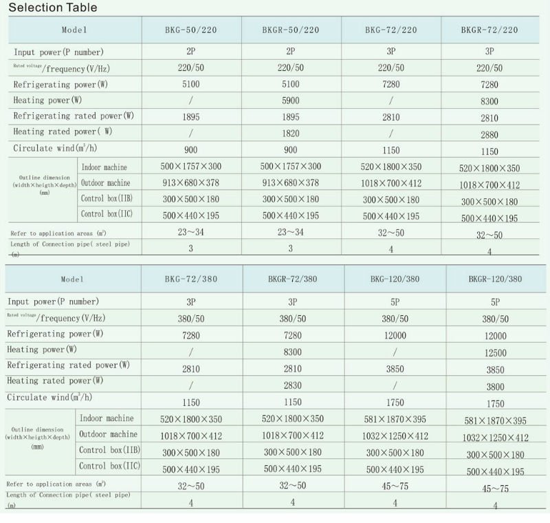
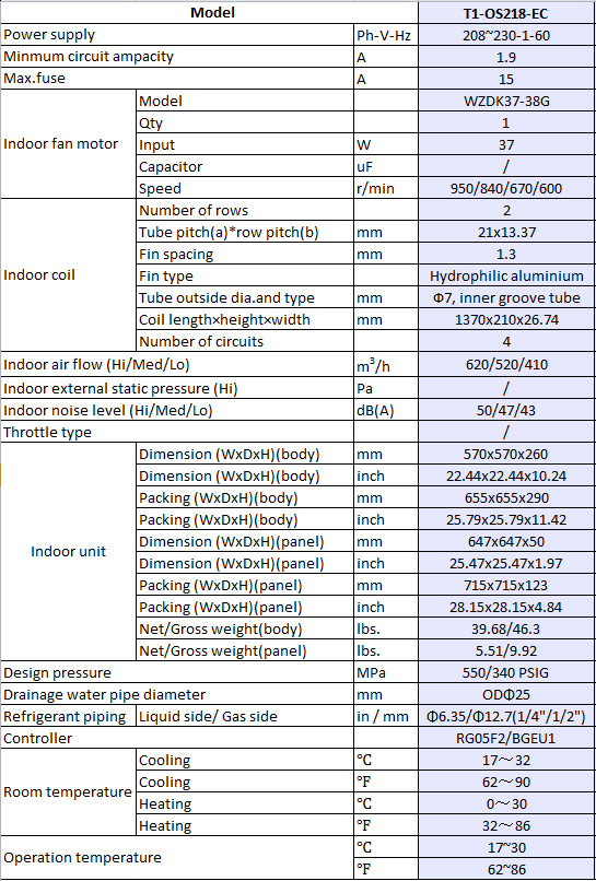
Exploded View of Indoor Unit 6 8. Part List of Indoor Unit 7 9. Exploded View of Outdoor Unit 9 Part List of Outdoor Unit 10 Wiring Diagrams 11 Field Electrical Connections Matching 13 Northwell Health®’s Huntington Hospital will save 10% on energy costs annually, about $,, and earn more than $, in additional energy rebates from Public Service Energy Group due to the installation of a Carrier® 30XV air-cooled chiller system.BTU Dual Zone Ductless Mini Split x 2 Ceiling CassetteWiring diagram for Carrier FA4BNF Indoor Unit – Fixya
