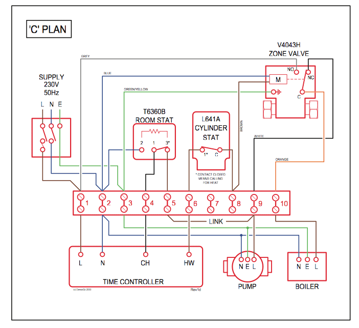
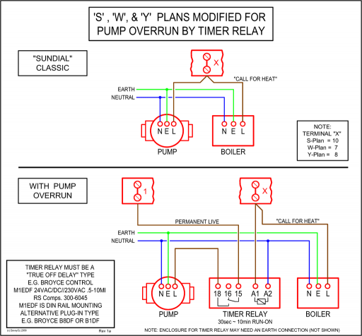
38AQS Field Wiring Diagrams. The CLO locks out the compressor to prevent short cycling on Printed Circuit Board.
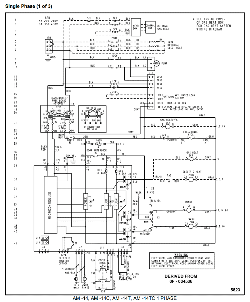
QT . master control, Carrier Part No.
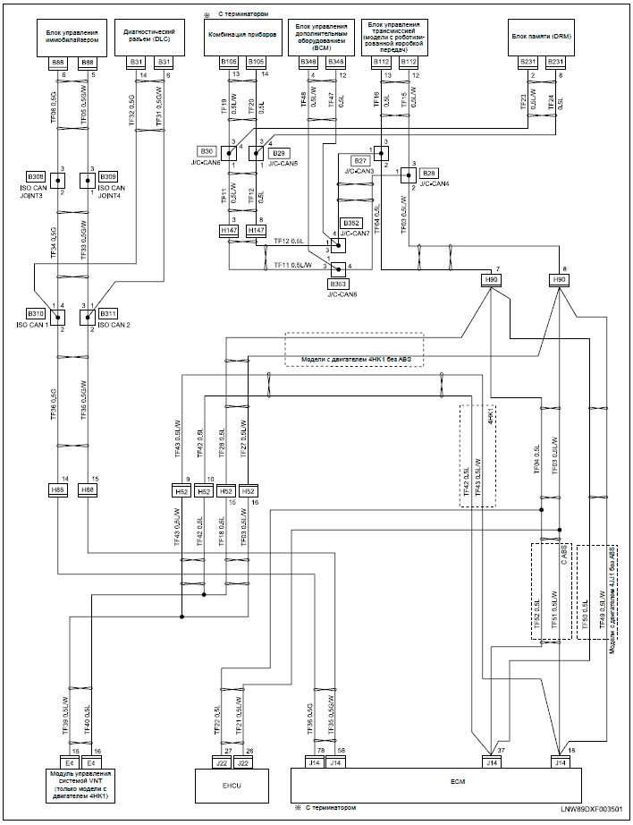
CCH WORKED AS A SAFTEY! and as for me being wrong in this ask carrier if they laugh at your ingnorance look at a wiring diagram.
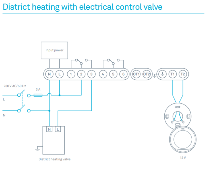
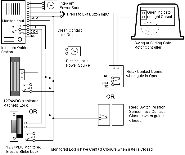
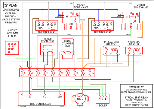
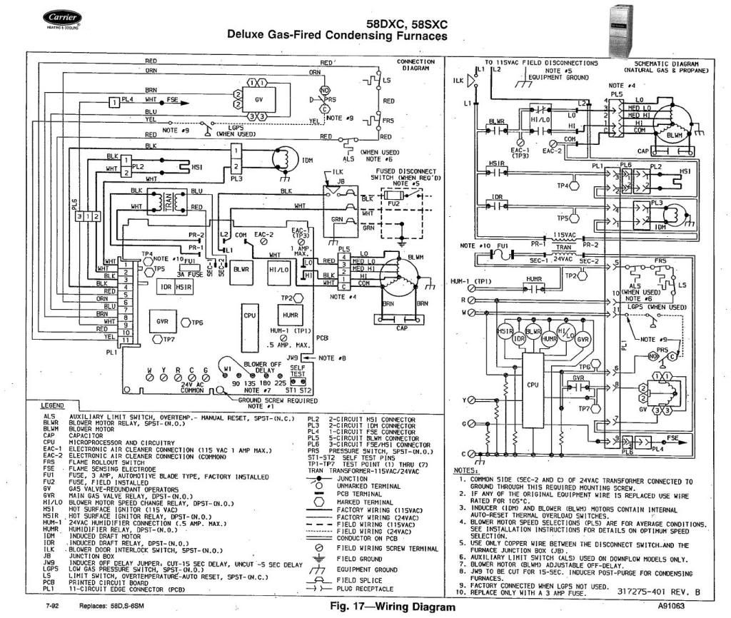
dose anyone know how to temp bypass a 4 wire carrier clo board. Look at the wiring diagram. Takes one jumper between two points without.
To verify compressor lockout logic: a. Disconnect CLO sensor wires connected to CLO1 at.
the control board. Check wires for continuity.
If there. is no continuity.
I have a rooftop Carrier package unit and cant get compressor(s) to run I haven’ t pulled up a diagram on it yet, but do you know if it has a lock out relay board? .
Put the new CLO’s on, but found that CLO1 and CLO 2 wires were crossed.Need help with Carrier package unit troubleshooting. maybe 2 X 3″ that is the compressor lock out relay or CLO on the diagram.
But I doubt you would have 2 of them bad. Now, when switch to Cool mode the outdoor compressor will not start.
I suspect the control board wiring is wrong. View and Download Carrier NP installation, start-up and service instructions manual online. Single Package Heating and Cooling Units.
NP Air Conditioner pdf manual download. Also for: 48dj, 48dk, 50dj, 50dk, 50dw, 50dy, 50nb, 48np, 50np.
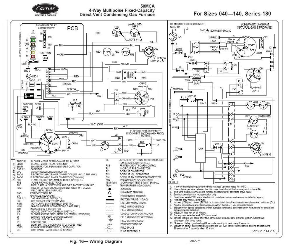
The CLO locks out the compressor to prevent short cycling on compressor overload and safety devices. Before replacing CLO, check these devices. Remove jumper between RC and RH.
Defrost cycle time is factory set at 30 min. UNIT LABEL DIAGRAM Unit 38AQS V-Ph-Hz Label Diagram No.
Schematic Figure Component Arrangement Figure , 2 GENERAL This publication contains Wiring Diagram information for the 30XA air-cooled liquid chillers with electronic controls. These chillers are equipped with ComfortLink™ con- trols and electronic expansion valves. component arrangement on the kit wiring diagram.
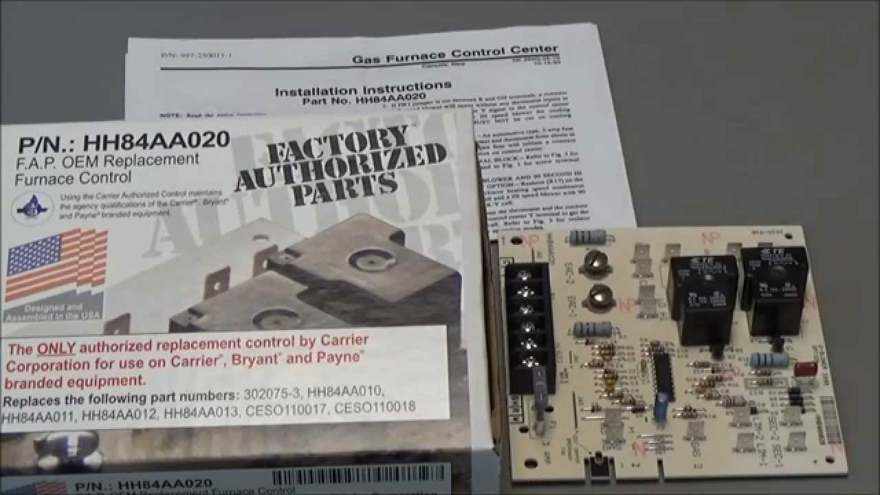
See Fig. 1. 4.
Route brown wire to terminal block TB3 and connect to any terminal of TB3. See Fig.
2. 5.
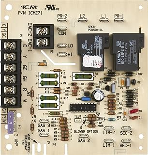
Route wires and to the compressor lockout (CLO) board. a.
For the first stage compressor, this .Google Discussiegroepencarrier clo board