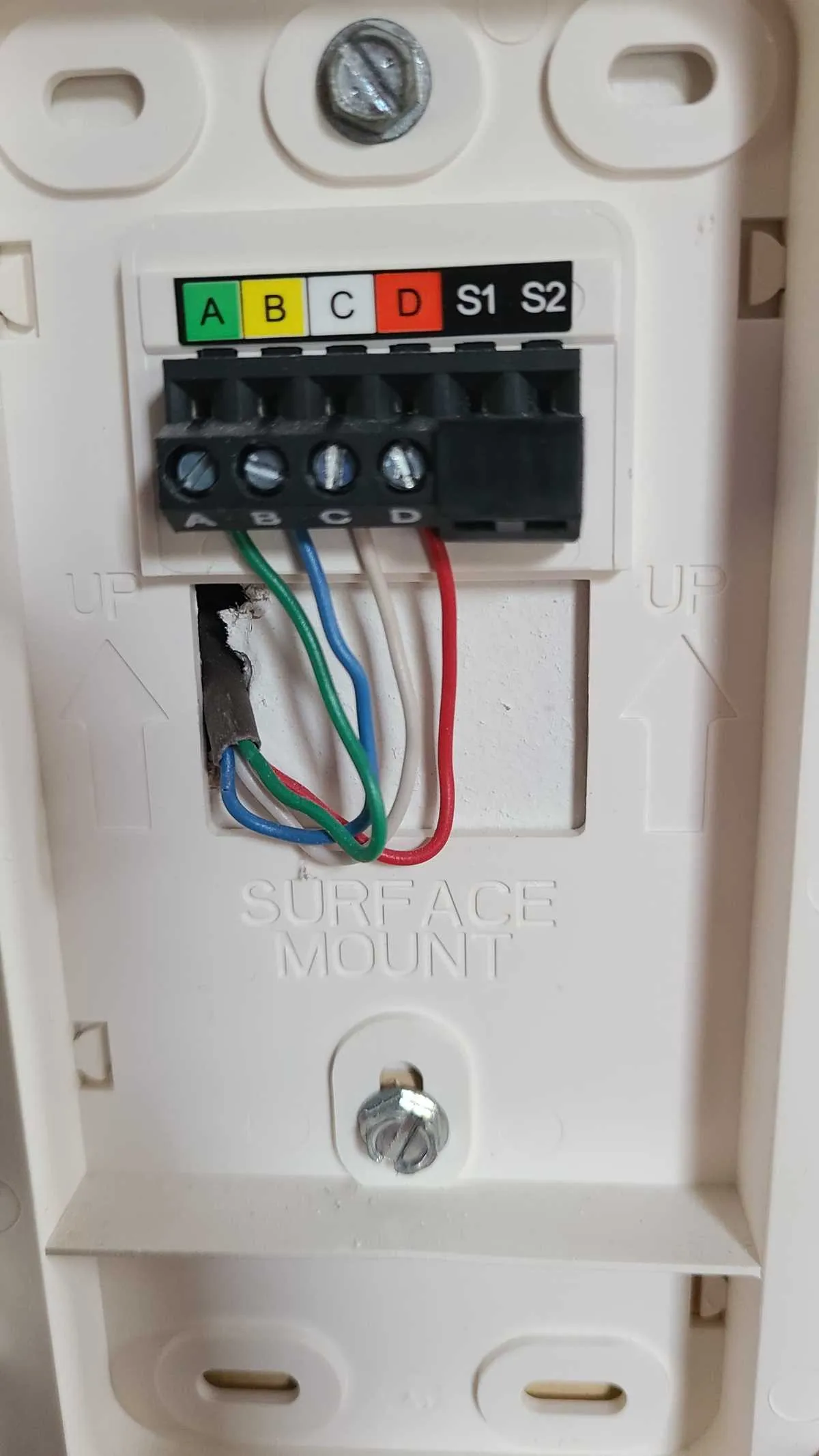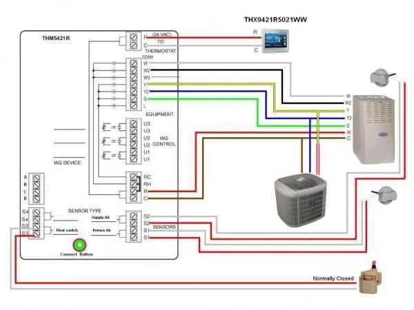
To ensure proper operation of your HVAC system, understanding the connection between the main control unit and the climate management system is crucial. Begin by identifying the terminals on the main unit, typically marked with specific letters indicating their function: R for power, C for common, and various others for heating, cooling, fan, and emergency functions.
Start with the R terminal, where the 24V power supply connects. Next, connect the C terminal to the neutral side of the power system to complete the circuit. This setup ensures a stable current flow, preventing any electrical malfunctions.
Each function, such as cooling or heating, has its designated terminal: Y for cooling, W for heating, and G for the fan. For systems with auxiliary heating or multi-stage cooling, additional wiring may be necessary. Ensure each wire is securely connected to its appropriate terminal to avoid operational issues.
Double-check the integrity of your connections and confirm the wiring matches the system’s requirements. For advanced configurations, such as multi-stage or smart control systems, consult the manufacturer’s guide for specific wiring needs. Proper installation will not only enhance efficiency but also prolong the lifespan of your HVAC unit.
Essential Wiring Setup for Your Climate Control System
Ensure proper connection of the terminal blocks for optimal performance by following these steps:
- Red (R): Connect this to the power supply for the system. This wire provides 24V power to your unit.
- C (Common): The common wire completes the circuit, allowing continuous power flow.
- W (Heating): This terminal controls the heating function. Connect it to the heating element or furnace.
- Y (Cooling): This wire directs cooling commands from the controller to the air conditioner or cooling unit.
- G (Fan): Attach to the fan control to manage the ventilation settings, which trigger fan operation.
- O/B (Reversing Valve): For heat pump systems, this terminal manages the change between heating and cooling modes.
- Y2 (Cooling Stage 2): In advanced systems with multiple cooling stages, this terminal connects the second cooling unit.
Before starting, ensure the power to the system is completely shut off. Cross-check each wire color with the corresponding terminal as per the system’s requirements. For added safety, use insulated connectors and verify that all terminals are firmly connected to avoid electrical shorts or malfunctions.
After all wires are connected, test the system to verify proper operation. Ensure that the cooling, heating, and fan settings respond correctly to changes in temperature control.
How to Identify Wire Connections for HVAC Control Units
Start by turning off the power to your HVAC system. Use a screwdriver to remove the cover plate from the control panel. Inside, you will find a set of color-coded wires attached to terminals. Each terminal is usually marked with a letter or symbol indicating its function. Here’s a guide to help you identify the connections:
Red Wire (R): This is typically the 24-volt power supply wire. It connects to the R terminal, which powers the unit.
Yellow Wire (Y): This wire is used for cooling. It should be connected to the Y terminal, which controls the air conditioner’s compressor.
Green Wire (G): This wire is for the fan and connects to the G terminal, controlling the blower motor.
White Wire (W): This wire controls heating and connects to the W terminal. It triggers the furnace to turn on when heating is required.
Common Wire (C): The C terminal is used for the return path of the 24-volt power supply, completing the circuit for some models that need constant power.
O/B Wire: This wire controls the reversing valve in heat pump systems. The O or B terminal may be labeled accordingly depending on the system’s design.
Double-check the connections and ensure the wires are securely placed in the correct terminals. If any wires appear loose or incorrectly connected, fix them before restoring power. Use a multimeter to verify voltage if you’re unsure of the wire’s functionality.
Common Electrical Issues and Solutions for Climate Control Devices

When facing improper operation, the most common problem is improper connections at the terminals. Ensure all wires are tightly connected to their respective points. Loose connections can result in malfunction or complete failure to operate the system.
If your system isn’t turning on or responding, check for issues with the power supply. Confirm the fuse is intact and the circuit breaker hasn’t tripped. Replace the fuse if needed and reset the breaker to restore power flow.
Another frequent issue is an incorrect wiring sequence. Double-check that each wire is linked to the correct terminal, particularly for heating and cooling functions. Mismatched terminals can lead to improper control of your system’s climate settings.
Interference or signal disruption can occur when the device has a poor connection to the heating/cooling unit. Inspect for any damaged or corroded wires, particularly in older installations. Replacing or repairing these wires can ensure a stable connection and proper communication between units.
If the system responds erratically, it could indicate a grounding issue. Confirm that the ground wire is connected properly, as a poor ground connection can cause instability in operations, including false readings or sudden shutdowns.
Lastly, a malfunctioning control unit might result from improper voltage levels reaching the internal components. Use a multimeter to check the incoming voltage and ensure it matches the required specifications. If there’s an imbalance, it may be necessary to replace the internal circuitry or adjust voltage settings to prevent further issues.
Step-by-Step Guide to Replacing the Thermostat Wiring in Carrier Units

Ensure the power is completely turned off before starting the process. This step is crucial to prevent any electrical hazards or damage to the system.
Begin by carefully removing the cover from the control unit. Most covers are clipped in place and can be easily detached. Once removed, take note of how the existing cables are connected to the terminals for reference.
Using a screwdriver, unscrew the terminal blocks that hold the wires in place. As you remove each wire, keep track of its position and color. This will make reconnecting them in the new unit much easier.
Next, check the condition of the cables. If any are frayed or damaged, replace them with new wires of the same gauge to ensure compatibility and safety. Proper insulation is key to avoiding shorts or system malfunctions.
Once the new wiring is in place, connect the wires to the corresponding terminals based on the reference notes you took earlier. Tighten the screws securely to ensure good contact and avoid loose connections that could cause intermittent issues.
After securing the new wires, reattach the control unit cover. Double-check all connections before restoring power to the system. Power it on and test the functionality by adjusting the settings on the unit to ensure the changes were successful.
If everything is operating correctly, the replacement is complete. If issues persist, verify the connections again or consult the manual for troubleshooting tips.