
Rj45 Wiring Diagram On Tia Eia a b Standards For Cat5e Cable RJ45 Ethernet Cable Wiring Diagram Rj45 Cat5e a Wiring. A pinout is a specific arrangement of wires that dictate how the connector is 8 pin connector used for terminating Cat5e or Cat6 twisted pair cable.
If you need to connect A equipment to B you can use a crossover cable. here some diagram for wiring rj45 schematron.orgdiagramcom/.
A Cat5e wiring diagram will show how Category 5e cable is usually comprised There are two common Cat5e cable wiring schemes, A and B, that are. Cat5 Wiring Diagram Printable, Cat5e Wiring Diagram PDF, Cat6 Wiring Diagrams, RJ45 Wiring-Diagram, B Wiring Diagram, Cat5e Wall.
Technical Specifications for TIA/EIA a & b Standards for CAT5e Cable Cat 5e jacks (diagram below right) may have a twist inside the jack to reduce.Cat5e Crossover Cables | Cat6 Crossover Cables. A good way of remembering how to wire a Crossover Ethernet cable is to wire one end using the TA standard and the other end using the TB .
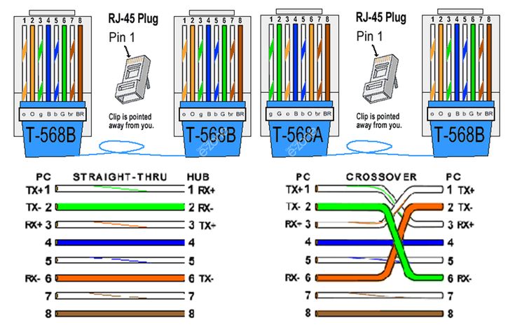
Cat 5 Network Cable Wiring Configuration Diagram Straightthru: Wire both ends identical, B or A. The only difference between A and B wiring is that pairs 2 and 3 (orange and green) are swapped.
If you are unsure which one to use then you should go with the B diagram. It is the B diagram that we demonstrate in this tutorial and the A wiring is shown in the diagrams .
TIA/EIAA and B are two standards for connecting Category 3 and Category 5 wire to connectors. Both are appropriate for high speed data, though B is .
For a crossover cable (rj45 wiring diagram), one end is EIA/TIA B and the other end is EIA/TIA A. Keep the end of the wires flat and trim their ends leaving about mm in length.
Insert the wires into the RJ plug while holding the connector or clip down.EIA/TIA A & B StandardRJ45 Wiring Diagram Ethernet Cable | House Electrical Wiring Diagram