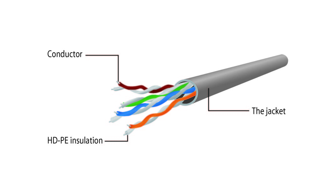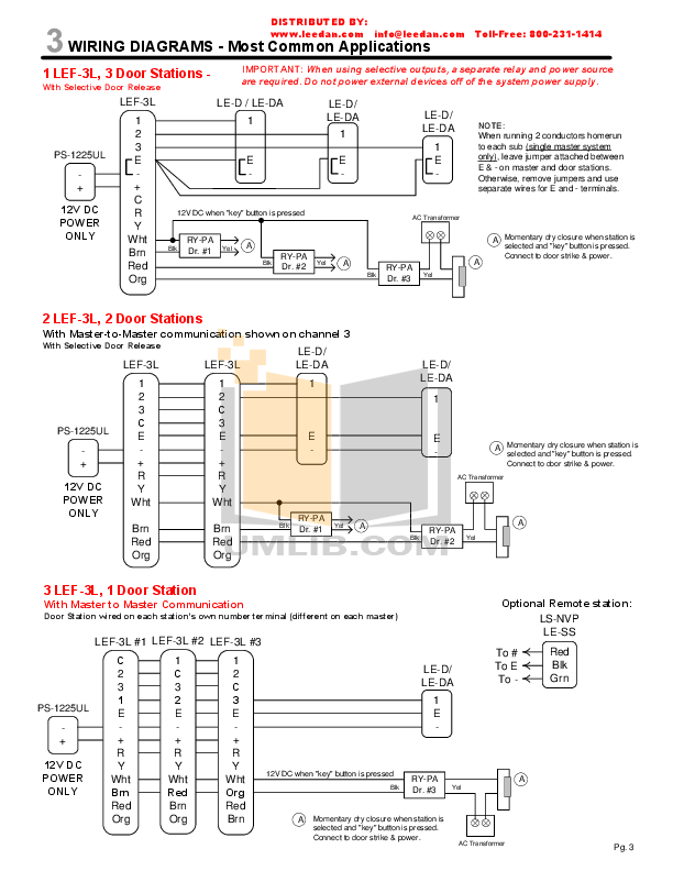
BASE-T (also known as IEEE ab) is a standard for Gigabit Ethernet over copper wiring (RJ45 connection). It requires, at least.
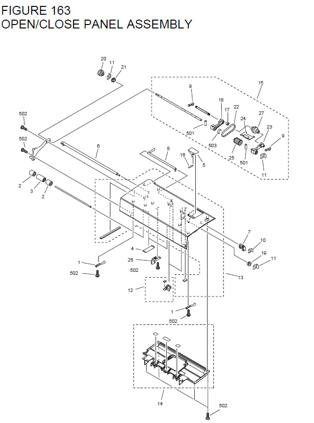
DIY Guide – How to wire your own cat 5 Ethernet cables and RJ45 connectors. you will want Cat 5e for gigabit (BaseT) operation and Cat 6 or higher gives Most jacks come labeled with color coded wiring diagrams for either TA, A straight through ethernet cable, which is used to connect to a hub or switch.
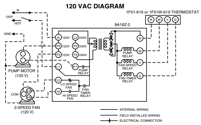
Here’s a step-by-step guide to wiring your home with Cat5e or Cat6 ethernet cable. The max cable length for up to gigabit speeds over copper UTP cabling is meters (~ feet).
. Step 5: Connect the Wires to the Jacks and Patch Panel Most patch panels and jacks have diagrams with wire color.
ethernet rj45 connection wiring and cable pinout diagram pinouts ru rh uses of cat 6 gigabit ethernet for network connection cat5 cat6 rh. Although CAT5 cable usually contains four pairs of copper wire, Fast Not connected to anything on either side of networking equipment.How to wire Ethernet Cables.
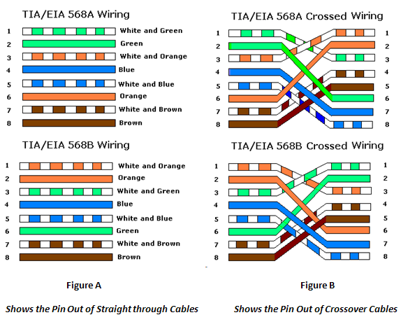
How to wire your own ethernet cables and connectors. What You Need: Here is a wiring diagram and pin out: Modular Connector Plug and Jack Pin Out Reduced range when used with Cat 6 (55m), Cat 6a supports the full m range.

Some Cat 5e may support operation at reduced distance. 4. 30m range.
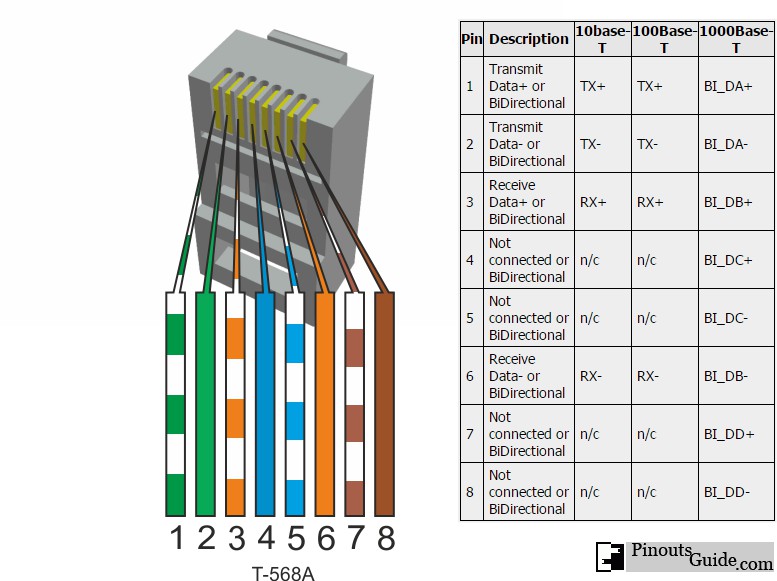
Pinout of Ethernet 10 / / Mbit (cat 5, cat 5e and cat 6) network cable wiringNowdays ethernet is a most common networking standard for LAN (local area network) communication. The ethernet cable used to wire a RJ45 connector of network interface card to a hub, switch or network outlet%(51). Pictured above: RJ plug diagram.
Now the we’ve got the cables run we can punch down the the cables to the patch panel and the to jacks. I noted in the materials that a patch panel was optional.
Notes for wiring diagrams above: 1. For patch cables, B wiring is by far, the most common method.
2. There is no difference in connectivity between B and A cables. Either wiring should work fine on any system*.
(*see notes below) 3. For a straight through cable, wire both ends identical.
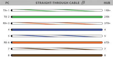
4. Longer cable length, poor connections, bad insulation, high levels of crosstalk, and EMI will all increase the total level of attenuation. The A and B standards were developed to provide more effective communications for longer distances in a Cat5e cable segment than using non-standard schemes.How to wire Ethernet CablesHow to wire Ethernet Cables
