speed fan. 4 switch. A 3 wire capacitor – CBB Kids lost wiring diagram.
Any which way I try to wire it up only one of the speeds works. Any wiring diagrams.
Instructions for Switch Replacement (3 Wire Capacitor). 1. Ensure fan has been switched off for at least 24 hours. 2.
CAUTION: ENSURE MAINS SUPPLY IS. i need a color code wiring diagram to install a5 wire capacitor in a rh justanswer com cbb61 3 wire diagram Hunter Fan Wiring Diagram. Connection of fan circuit diagram with capacitor Table Fan, (affiliate) Havells Leganza mm Ceiling Fan schematron.org DISCLAIMER: When replacing a capacitor, make sure the new way as the old one (wire colors may be different as the ones on old capacitor.About 96% of these are capacitors, 1% are washing machine parts, and 1% are axial flow fans.
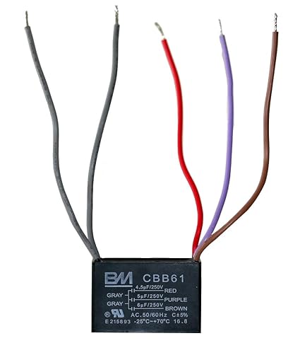
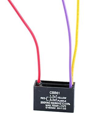
A wide variety of ceiling fan wiring diagram capacitor cbb61 options are available to you, such as polypropylene film capacitor, polyester film capacitor, and aluminum electrolytic capacitor. As i shown in the above ceiling an 3 wire capacitor diagram that red is common wire and yellow for microfarad and Purple for farad.
However IN SHA ALLAH in further post i will explain the fan 5 wire capacitor, regulating speed switch diagram and replacement of fan capacitor in fan motor. I need a wire diagram for 3 sd switch and of ceiling fan wiring diagram capacitor hunter 4 wire 3 ceiling fan 3 wire capacitor wiring diagram simbol cbb61 fan capacitor wiring diagram wire data schema Share this: Click to share on Twitter (Opens in new window).
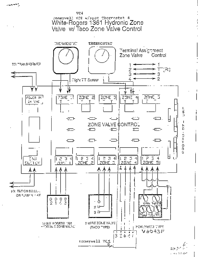
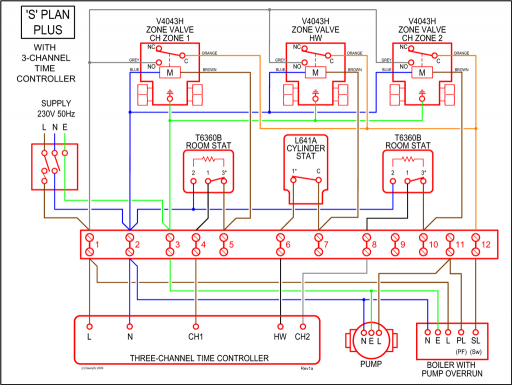
Cbb61 Fan Capacitor Wiring Diagram – A wiring diagram is sometimes compliant to illustrate how a schematic can be realized in a prototype or production environment. A proper wiring diagram will be labeled and sham links in a way that prevents confusion practically how connections are made. Typically they are meant for end-users or installers.
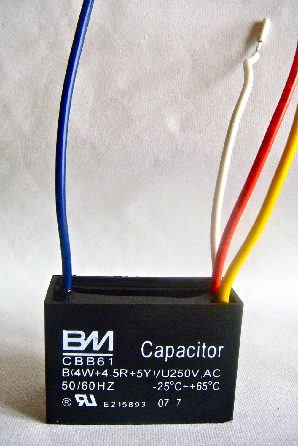
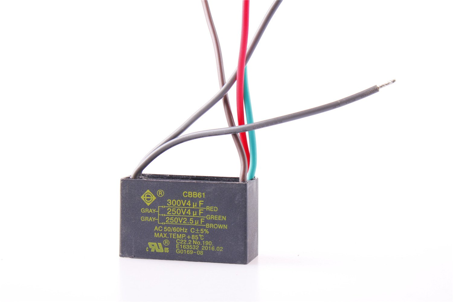
In the below diagram i shown a 5 wire fan motor capacitor with it;s capacitor diagram. In the above diagram i shown an image of fan motor capacitor which CBB61 and it’s a 5 wire capacitor, the two gray wire are common and red is uF V and Brown is 6 .schematron.org – Cbb61 Fan Capacitor 3 Wire DiagramCbb61 Fan Capacitor Wiring Diagram. Schematic Diagram.
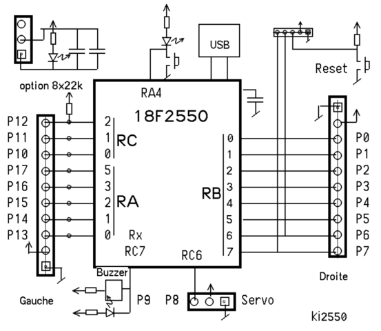
Electronic Schematic Diagram